Elements in the thermal solver
The thermal solver uses elements to calculate conductive, convective, and radiative conductances, as well as hydraulic resistances.
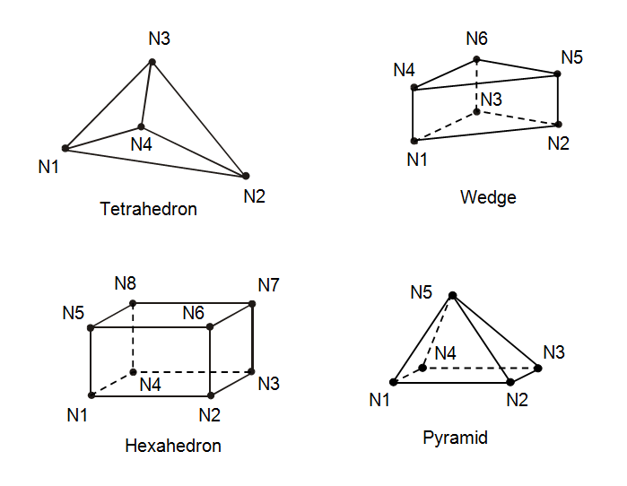
The element type and the number of nodes (ranging from 1 to 8) define the shape of an element. Elements can take various forms, including spherical lump masses, cylindrical beams, triangles, quadrilaterals, tetrahedra, wedges, or hexahedra. The thermal solver supports the following type of element described in sections.
Surface elements
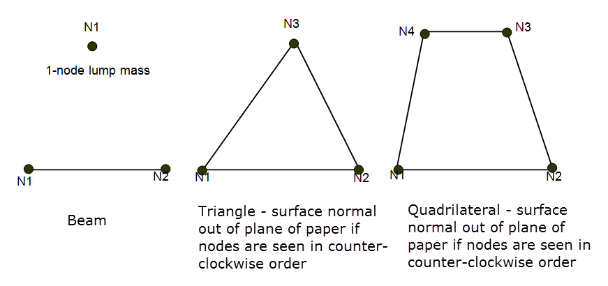
A surface element supports capacitance, conductive conductance, radiative conductance, and thermal coupling calculations.
The orientation of a surface element's surface normal is determined by the ordering of its nodes. If the element is so viewed in a counter–clockwise order, the element surface normal points towards viewer.
Solid elements
Solid elements are used to model tetrahedron, wedge, or hexahedron. Specific order required for non-tetrahedron solids. For wedges, the 4th node must be above the 1st node. For hexahedra, the 5th node must be above the 1st node.
Midside type
Midside type specifies that the element is parabolic and lists the midside nodes. If a parabolic element is specular and if ray tracing is performed, the curvature of the element will be taken into account for the calculation of the reflected ray direction.
Hydraulic elements
Hydraulic elements model mass and heat transport, including free and forced convection mechanisms, in 1-dimensional duct network fluid flow. Each hydraulic element is part of two coupled networks: the pressure/flow hydraulic network and the temperature/heat flow thermal network. The element connects to the hydraulic network with flow resistances and to the thermal network with convective and one-way conductances. These networks are bidirectionally coupled because convective and one-way conductances depend on the mass flow through the element, while buoyancy forces, density, and flow resistances depend on temperature.
1-Node hydraulic elements
1-node hydraulic elements model heat transfer and pressure drops in 1-D duct flow networks. They define the fluid and duct cross-sectional properties.
- FLOWSEC
- Defines the cross-sectional properties (area and hydraulic diameter) at its location.
- BLSTART
-
Similar to a FLOWSEC element but also defines the start of the boundary layer for convective conductance calculations.
- AMBIENT
- A large area pressure and temperature sink element used to define a flow boundary condition. Models with hydraulic elements must include at least one AMBIENT element. The hydraulic environment (ambient temperature, static pressure) must be defined to set boundary conditions for AMBIENT elements. AMBIENT elements at the ends of flow branches will be automatically created unless a FLOWSEC or BLSTART element is specified there.
2-Node hydraulic elements
2-node hydraulic elements define the total pressure drop or rise across them. The element's center of gravity (CG) connects to its ends with equal flow resistances to model pressure drops and one-way conductances to model heat transported by the fluid. Temperatures and total pressures are computed at both the CG and the ends of hydraulic elements. Gas densities are computed using the Ideal Gas Law. The nominal and initial flow directions are from node 1 to node 2. During each thermal steady-state iteration or transient time step, the complete hydraulic element network is solved in a separate iterative solution loop.
- DUCT
- Represents a straight duct, diffuser, or nozzle. The thermal solver computes length-dependent flow resistances for these elements.
- FLOWRES
- Models losses over elbows, exits, entrances, and orifices. Similar to a DUCT element but with length-independent flow resistance.
- FANPUMP
-
Specifies a flow boundary condition such as total pressure rise, mass flow, volumetric flow, and flow velocity.
The center of each 2-node hydraulic element automatically connects to the upstream and downstream 1-node hydraulic elements with two equal hydraulic flow resistances and one-way fluid flow thermal conductances. Optionally, convective conductances between 2-node hydraulic elements and other thermal elements may be defined.
Flow branchesA flow branch is a series of connected 2-node hydraulic elements ending in either a 1-node hydraulic element or a junction with two or more flow branches. The same forward direction should be specified for all 2-node hydraulic elements in a flow branch, from node 1 to node 2. If there is a direction inconsistency, the orientation of a hydraulic element will be automatically reversed, and a warning message will be given. Flow reversals due to pressure changes will also be automatically computed.
Each hydraulic element must have its cross-sectional and flow properties defined. For a 2-node hydraulic element, these are defined by the 1-node elements at its ends. To define cross-sectional and flow properties for a flow branch, it is sufficient to specify a single 1-node hydraulic element at the most upstream location. New downstream FLOWSEC hydraulic elements with the same cross-sectional and fluid properties will be automatically created until a new FLOWSEC or BLSTART element is encountered.
Stream elements
Stream elements are similar to hydraulic elements in that they describe advective heat transfer due to fluid mass flow, but they give a more flexible way to directly control the fluid mass flow distribution with only minimal user input for the element properties and boundary conditions. Unlike the regular hydraulic elements they do not have flow resistance, cross-sectional, or fluid conduction properties and do not model pressure drops. Stream elements may not have fluid flow connections (may not share a node) with regular hydraulic elements.
For stream elements that do not have explicitly defined mass flows, the mass flows are solved for so that to best match all the mass flow boundary conditions in a given stream network while optimizing mass flow continuity (minimizing the mass flow imbalances at the junction points) throughout the network and, for under-constrained problems, also optimizing flow equality between different inflow or outflow branches of each network junction. Mass flow imbalances at network junctions are permitted (over-constrained problems with conflicting boundary conditions), but a warning is issued for junctions where such imbalances are significant (greater than 1 percent). To prevent a mass flow imbalance at a given junction from causing a heat flow imbalance in the thermal solve, a compensating mass flow injection or loss is added internally at that junction, assuming the temperature of the extra mass flow to be the same as the calculated temperature at the junction.
Because of their unset cross sectional properties, stream elements have undefined fluid velocities and Reynolds numbers. The stream fluid material capacitance is used for calculating advection conductances, but not for modeling stream element heat capacitances, which are taken to be zero, in transient runs.