Card 6e - Thermal Coupling Request (NEARx)
This optional card connects each of the N1 elements to the nearest of the N2 elements.
Parameters: L, N1S, N1F,
N1D, N2S, N2D,
HN1, KODE, EXP,
P1, VX, VY,
VZ
The algorithm calculating which element is the nearest assumes the elements are parallel to each other, and partially or wholly overlap.
The area for the thermal coupling ATC is always based on the primary
selection area. It is calculated with the assistance of the Card 2a/Card 6f MESH
parameter. Each element N1 is subdivided into MESH2*NV
sub-elements, according to the approach described on Card 2a, where NV is the number of
nodes of N1.
For all the NEARx options described below, ATC is by default based on the areas of the primary sub-elements. If the OVERLAP or OVRFLP options are used, then ATC is the area of overlap between the primary element and the secondary element.
If the thermal coupling request is not preceded by a Card 6f MESH card containing the term OVERLAP or OVERFLP, then each primary element sub-element is coupled to the nearest secondary element. For area-dependent conductances, the area, ATC(N1), used for each coupling is based only on the proximity test and it is the area of the sub-element of the N1 element. The resulting conductances from the sub-elements of the N1 element to the same N2 element are summed.
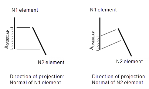
If the Card 6f MESH card preceding a thermal coupling request contains the term OVERLAP, then calculations are performed with the proviso that no thermal couplings are created for elements that do not overlap. An overlap test between each sub-element of each element from the N1 group and the elements in the N2 group is performed. The overlap test is done by projecting the primary element onto the secondary element. The normal used for the projection of the primary element is selected according to the rules described in Card 6f Mesh. Each sub-element of the primary selection is coupled to the nearest secondary overlapping element. For area-dependent conductances, the area ATC(N1) used for each coupling is the area of the sub-element of the N1 element that has an overlap with an element from the secondary selection. The coupling is dependent on the normal used for the projection of each primary element onto the secondary group. The resulting conductances from the sub-elements of the N1 element to the same N2 element are summed.
Similar rules apply when the thermal coupling request Card 6e is preceded by a Card 6f MESH card containing the expression OVERFLP, except that the primary N1 and secondary N2 groups are interchanged if the average area of the primary group is greater than the average area of the secondary group. The option to select the primary or the secondary normal for the overlap test is not available in this case. If the primary and secondary selections are flipped, the original primary normal is used for the overlap test and the area ATC is based on the original secondary selection area. The use of OVERFLP is no longer recommended.
The minimum MESH value is 1, resulting in 4 sub-elements for a quadrilateral element.
MESH = 0 defaults to MESH = 1. The maximum MESH
value is 5, resulting in 100 sub-elements for a quadrilateral.
If the Card 6f MESH RESET option is used, no subdivision is performed, and only a single conductance is calculated for each element. With this option, false diffusion will not occur. False diffusion is the phenomenon of unintended lateral heat transfer between adjacent N1 elements joined to the same N2 element.
L
L is the code AREA (or 11)
The NEARx (recommended) options connect the N1 elements to the nearest of the N2 elements.
N1S
Defines the N1 elements.
If N1S is an element number, the N1 elements start with N1S, end with N1F, and are
incremented by N1D. N1D = 0 defaults to
N1D = 1.
If N1S is a group name (the preferred option), N1F and N1D must be 0.
N2S
Must be a group name. For each element in the N1 set, the elements to be coupled to it are chosen from this group, based on either the overlap or the proximity algorithm.
N2D
If N1S and N2S are both group names, N2D is the ID number of the
Card 9 DESCRIP Card associated with this request.
HN1
Is a coefficient associated with element N1. HN1 = 0 defaults to
1.
EXP
Is a parameter associated with the NEAR, NEARA, NEARF, and NEARCx options. Otherwise, it should be blank.
KODE = NEAR
NEAR (or 5) creates a linear conductance = HN1.
EXP is an optional table or expression number for a conductance
multiplier. The dependent variable on its TABTYPE Card must be COND.
KODE = NEARA
NEARA (or 8) creates a linear conductance = ATC(N1)*HN1
ATC(N1) is the area of the overlap of N1 onto N2.
EXP is an optional table or expression number for a conductance
multiplier. The dependent variable on its TABTYPE Card must be COND.
KODE = NEARAFU
NEARAFU (or 38) does exactly the same as NEARA, except the N2
elements must be hydraulic elements.
KODE = NEARA1W
NEARA1W (or 32) creates a linear 1-way conductance =
ATC(N1)*HN1
A*(N1) is the area of the overlap of N1 onto N2. The elements N2 are affected by the N1 elements, while the N1 elements are not affected by the N2 elements.
KODE = NEARA1WTOT
NEARA1WTOT (or 49) creates a linear 1-way conductance =
HN1*ATC(N1)/ATOT1.
ATC(N1) is the area of the overlap of N1 onto N2.
ATOT1 is the sum of the areas of all the elements N1. The elements N2 are affected by the N1 elements, while the N1 elements are not affected by the N2 elements.
KODE = NEARA1WTOT2
NEARA1WTOT2 (or 48) creates a linear 1-way conductance =
HN1*ATC(N1)/ATOT2.
ATC(N1) is the area of the overlap of N1 onto N2.
ATOT2 is the sum of all the overlap areas of N1 onto N2. The elements N2 are affected by the N1 elements, while the N1 elements are not affected by the N2 elements.
KODE = NEARAR
NEARAR (or 11) creates a radiative conductance parameter R.
If the emissivities of N1 and N2 elements are table-dependent, R is adjusted at run-time.
where:
efirst(N2)is the first emissivity value in the table for element N2.e(N1)is the emissivity value for element N1.e(N2)is the emissivity value for element N2.ATC(N1)is the area of the overlap of N1 onto N2.HN1is the specified gray body view factor from N1 to N2.
KODE = NEARAR2
NEARAR2 (or 37) creates a radiative conductance parameter
R.
where:
ATC(N1)is the area of the overlap of N1 onto N2.HN1is the (effective emissivity of N1) * (gray body view factor from N1 to N2).
KODE = NEARAR3
NEARAR3 (or 40) creates a radiative conductance parameter
R assuming the N1 and N2
elements lie on flat parallel plates very close to each other.
If the emissivities N1 and N2 are table-dependent, the value of R is adjusted at run-time.
where:
ATC(N1)is the area of the overlap of N1 onto N2.efirst(N1)is the first emissivity value in the table for element N1.efirst(N2)is the first emissivity value in the table for element N2.e(N1)is the emissivity value for element N1.e(N2)is the emissivity value for element N2.
KODE = NEARAS
NEARAS (or 9) creates a conductance = ATC(N1)*HN1 in
series with the already existing linear conductance between N1 and N2, thereby
reducing it.
ATC(N1) is the area of the overlap of N1 onto N2.
KODE = NEARF
NEARF (or 14) creates a free convection conductance between N1 and
N2. Heat flow through it is calculated by:
ATC(N1) is the area of the overlap of N1 onto N2. EXP = blank defaults to .25.
KODE = NEARLP
NEARLP (or 18) creates a linear conductance = LENGTH(N1)*HN1.
N1 must be a beam element.
EXP is an optional table or expression number for a conductance
multiplier. The dependent variable on its TABTYPE Card must be COND.
KODE = NEARM
NEARM (or 13) creates a perfect contact coupling between N1 and N2
by imposing an equality constraint using the penalty method.
KODE = RL
RL is the perpendicular distance between N1 and N2. N1 and N2 should
lie on parallel planes.
- ATC(N1) is the area of the overlap of N1 onto N2.
EXPis an optional table or expression number for a conductance multiplier.- The dependent variable on its TABTYPE Card must be COND.
NEARRES
NEARRES (or 31) creates a linear conductance =
ATC(N1)/(HN1∗ATOT1).
ATC(N1) is the area of the overlap of N1 onto N2.
ATOT1 is the sum of the areas of all the elements N1.
EXP is an optional table or expression number for a conductance multiplier. The dependent variable on its TABTYPE Card must be COND.
NEARRES2
NEARRES2 (or 47) creates a linear conductance =
ATC(N1)/(HN1∗ATOT2).
ATC(N1) is the area of the overlap of N1 onto N2.
ATOT2 is the sum of all the overlap areas of N1 onto N2.
EXP is an optional table or expression number for a conductance multiplier. The dependent variable on its TABTYPE Card must be COND.
NEARS
NEARS (or 10) creates a conductance = HN1 in series with the already
existing linear conductance between N1 and N2, thereby reducing it.
NEARTOT
NEARTOT (or 30) creates a linear conductance =
HN1∗ATC(N1)/ATOT1.
ATC(N1) is the area of the overlap of N1 onto N2.
ATOT1 is the sum of the areas of all the elements N1.
EXP is an optional table or expression number for a conductance multiplier. The dependent variable on its TABTYPE Card must be COND.
NEARTOT2
NEARTOT2 (or 46) creates a linear conductance =
HN1∗ATC(N1)/ATOT2.
ATC(N1) is the area of the overlap of N1 onto N2.
ATOT2 is the sum of all the overlap areas of N1 onto N2.
EXP is an optional table or expression number for a conductance multiplier. The dependent variable on its TABTYPE Card must be COND.
NEARVF
NEARVF (or 28) writes a black body view factor on file VUFF with a
magnitude A(N1)∗HN1/AN1.
A(N1) is the area of the overlap when N1 is projected onto N2, and A(N1) is the full area of element N1.
Code example
AREA BOXTOP 0 0 BOARD1 0 1.6 NEARA
$ CONDUCTANCES ARE CREATED BETWEEN THE ELEMENTS OF
$ BOXTOP AND THE NEAREST ELEMENTS OF BOARD1,
$ MAGNITUDE = AREA(BOXTOP)(1.6)