Card 2a - Program Control
This mandatory card defines thermal solver control parameters.
Parameters: M, N, MESH,
RK, IST (obsolete), KSP,
SIGMA, PSUN, IA,
TLIN, PIR
All parameters on Card 2a must be defined. If a parameter is not applicable, it should be set to zero.
M
M defines which modules are to be executed in the thermal solver.
Different values of M can be combined to run multiple modules simultaneously. For
example, if M = 3, this means M = 1 + 2, and both the COND and
VUFAC modules will be executed.
M = 0executes modules MAIN, DATACH, ECHOS. This option is always triggered and performs data checking.M = 1executes module COND. It computes capacitances, conductive conductances, and hydraulic resistances from geometry. Two methods for calculating conductances are available: the element center method and the element CG method. The CG method, which is recommended, can be specified with a Card 9 PARAM COND NEW option.M = 2executes module VUFAC. It computes view factors, solar view factors, Earth view factors, albedo factors, and thermal couplings. For this option, you also need to specify Card 6 Request.M = 4executes module GRAYB. It computes radiative conductances from view factors. If there are no Card 6 view factor requests, and no restart run (no MODLF or VUFF files present), then the GRAYB module is not executed.M = 8(Obsolete) executes module GRAYB. It computes the solar spectrum gray body view factor matrix from view factors, which can be used to calculate solar spectrum heat loads in the POWER module. Any existing solar spectrum gray body view factor matrix on file VUFF will be overwritten. This is an obsolete option, which is not recommended.M = 16(Obsolete) executes module GRAYB. It computes the IR spectrum gray body view factor matrix from view factors, which can be used to calculate IR spectrum heat loads in the POWER module. Any existing IR spectrum gray body view factor matrix on file VUFF will be overwritten. This is an obsolete option, which is not recommended.M = 32executes module POWER. It computes collimated (sun) solar spectrum heat loads. Solar view factors, view factors, and the PSUN parameter are necessary for this calculation. If there are no Card 6 solar spectrum view factor (solar view factor, orbital view factor, heat flux view factor) requests, and it is not a restart run (i.e., there are no files MODLF or VUFF present), then the POWER module is only entered but not executed.M = 64executes module POWER. It computes IR spectrum heat loads. Earth view factors, view factors, and the PIR parameter are necessary for this calculation. If there are no Card 6 solar spectrum view factor (solar view factor, orbital view factor, heat flux view factor) requests, and it is not a restart run (i.e., there are no files MODLF or VUFF present), then the POWER module is only entered but not executed.M = 128executes module POWER. It computes diffuse solar spectrum (e.g., albedo) heat loads. Albedo factors or heat flux view factors, view factors, and the PSUN parameter are necessary for this calculation. If there are no Card 6 solar spectrum view factor (solar view factor, orbital view factor, heat flux view factor) requests, and it is not a restart run (i.e., there are no files MODLF or VUFF present), then the GRAYB module is only entered but not executed.
N
N controls the input/output format. You can specify different
options by setting the value of N. Multiple options can be combined by summing their
corresponding codes.
N = 0specifies that no options are selected.N = 8specifies NASTRAN format input, where all of Card 4 is a NASTRAN bulk data deck.N = 16specifies NASTRAN format output. If the Analyzer is run, NASTRAN element temperatures are written on FMODLF file.N = 512specifies that the VUFAC module does not write the details of the view factor calculations to [Simulation name]_report.log in order to reduce its size.N = 1024specifies that Card 4 and 5 data is read from the VUFF file.
MESH
MESH defines the element subdivision for view factor shadowing, ray
tracing, and Card 6e thermal coupling calculations performed by the VUFAC
module.
Unshadowed view factors and solar view factors are calculated exactly, and are not affected by the MESH value.
MESH = 0specifies that no subdivision is performed.MESH = 1,2,3,4,5specifies each beam is subdivided into MESH line segments, and each planar element is subdivided into NV × MESH² triangular sub-elements, where NV is the number of nodes in the element.
The Card 6f MESH Redefinition overrides the MESH parameter value.
 Beam MESH = 0 |
 Triangle MESH = 0 |
 Quadrilateral MESH = 0 |
Beam MESH = 1 |
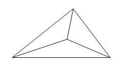 Triangle MESH = 1 |
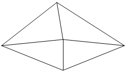
Quadrilateral MESH = 1 |
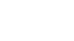
Beam MESH = 2 |
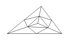 Triangle MESH = 2 |
Quadrilateral MESH = 2 |
RK
RK is used by the GRAYB module with Gebhart's method, but not with
Oppenheim's method, to either eliminate insignificant radiative conductances, or to
connect them to element's parameter KSP. A radiative conductance is considered
insignificant if its gray body view factors between two elements are less than the
absolute value of RK multiplied by the largest gray body view factor of either
element to a non-space element. The value of RK must be between –1 and 1.
RK > 0eliminates the radiative conductance, unless it is connected to a space element defined on a Card 5 SPACE.RK < 0connects the conductance to the KSP element, unless KSP is a space element.RK = 0defaults toRK = 1E-4.RK = 0.05reduces the number of radiative conductances without significantly impacting accuracy.
KSP
KSP is used by the GRAYB module to create residual view factors,
computed as 1-VFSUM for Gebhart's method when the view factors do not sum to unity.
Generally view factors do not sum to unity due to approximations made during the
shadowing calculation process.
KSP = 0creates self-view factors, calculated as 1−VFSUM, meaning that the elements are made to "see" themselves. This option is particularly useful when there are many low-emissivity elements present.KSP = 1000000adjusts the gray body view factors to compensate for residual view factors. However, this method is obsolete and does not work with Oppenheim's Method.KSP = NSPcreates view factors equal to 1−VFSUM to the element NSP. NSP must correspond to the space element number defined in Card 5d. If multiple enclosures exist, each enclosure is flagged to indicate whether it can "see" space. An enclosure is characterized as being able to "see" space if at least one element of that enclosure "sees" a space element. If an enclosure cannot "see" space, theKSP = 0option is applied for that enclosure. This prevents improper space couplings between enclosures that do not see space, allowing inside and outside enclosures to be safely mixed.KSP = 2000000is similar toKSP = NSP, but the space element number is obtained from the Card 5d Space Element.KSP = 3000000attempts to iteratively adjust the shadowed view factors proportionally in order to reduce residual view factors. This is the recommended option for most cases.
SIGMA
SIGMA is the Stefan-Boltzmann constant, expressed in approximate
units e.g., 0.1714×10⁻⁸ Btu/hr·ft2·R4 , or
5.6696×10⁻⁸ W/m2·K4, or
3.6577×10⁻¹¹W/in2·K4.
PSUN
PSUN is the collimated solar spectrum radiative source's (sun's)
power output per unit area arriving at the element. PSUN is used by the POWER module
in solar spectrum heat load calculations (M = 32 or M =
128). Typical values are 429±7 Btu/hr·ft2or 1353± 21
W/m2.
IA
IA is used if a sinda85 output is requested with Card 9 PARAM
SINDA85.
IA = 0creates a transient format output on file sinda85.dat.IA = -99990creates a steady-state format output on file sinda85.dat.
TLIN
TLIN is used by the MEREL module to linearize radiative conductances
during substructuring and Card 9 PARAM THIN model thinning operations, as (
T1+T2)(T12
+T22), where:
- T₁ represents the typical estimated absolute temperature of the elements to be eliminated.
- T₂ is the typical absolute temperature of their surrounding environment.
Only those conductances that are connected to both radiative and conductive elements are linearized.
PIR
PIR is the heat load per unit area leaving the surface of the Earth.
PIR is used by the POWER module (M = 64) to calculate Earth heat
loads. A typical value for PIR for Earth heat load calculations is 75
BTU/hr/ft2 or 236 W/m2.
Code example
7 0 1 0 0 84 1.713E–9 440 0 26463592 80 $ CARD 2A
$ The VUFAC, GRAYB and COND modules will be executed.