Thermal coupling methods
This article explains coupling methods that the thermal solver supports. You will learn element subdivision and projective intersection coupling methods, how to calculate overlapped area, understanding overlap projection direction, how to control coupling resolution, and visualize thermal coupling connections.
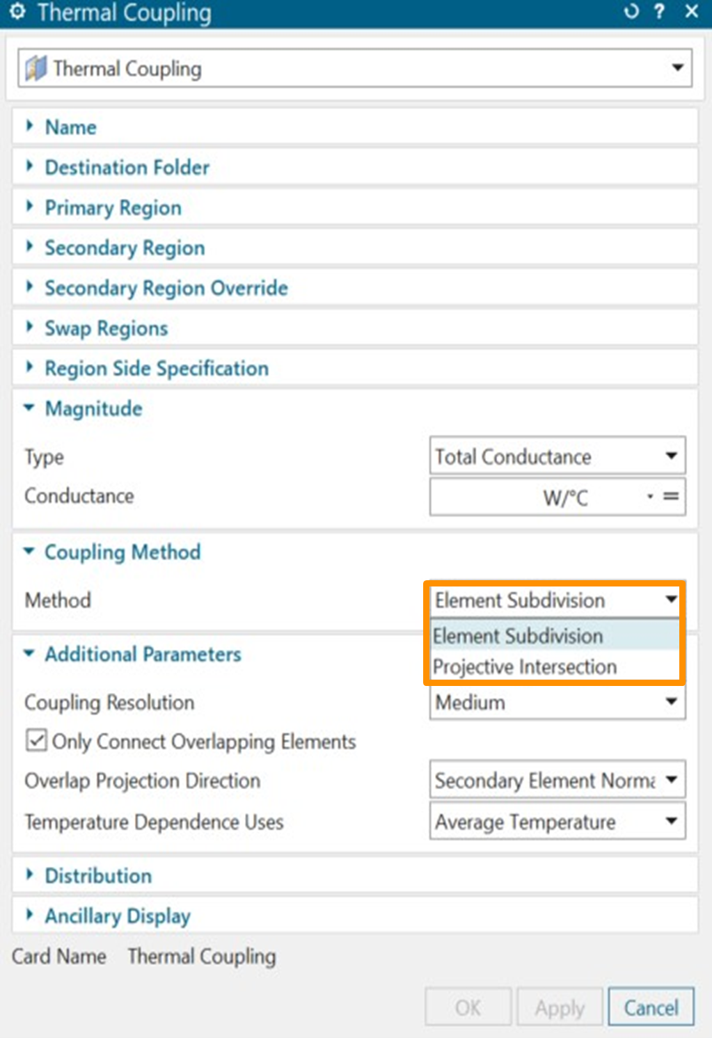
Understanding coupling methods
- Element Subdivision connects primary elements to secondary elements using the proximity or overlap method by dividing the primary elements into subelements, using the specified coupling resolution.
- Projective Intersection connects primary elements to secondary elements that overlap along a given projection direction. It computes the exact overlap area between the two sets of elements.
Generating conductances
Thermal couplings define a heat path from one set of elements to another, which can be spatially separated, and geometrically different.
In the thermal coupling based on proximity, the area for the thermal coupling is always based on the primary selection area.
Calculating overlapped area using element subdivision method
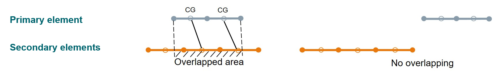
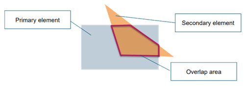
In the thermal coupling based on the overlap area, the thermal coupling area is the area of the sub-element of the primary element that has an overlap with an element from the secondary selection.
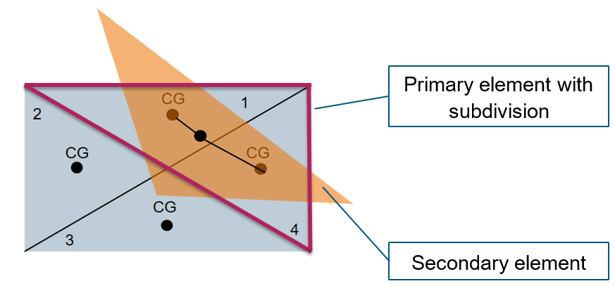
The area used for each coupling is the subelement area of the primary element, which overlaps with an element from the secondary selection. The CG of the primary sub-element must be inside the secondary element to have a connection. In the following example, the overlapping area is the area of sub-elements 1 and 4.
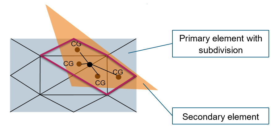
In the following example, there are four primary sub-elements that are connected to the secondary element. The overlapping area is now more accurate compared to the first example. The more we subdivide, the more accurate the overlapping area is.
Controlling thermal couplings between overlapping entities
You can control how the thermal coupling connection is found and created between primary sub-elements and secondary elements.
|
|
|
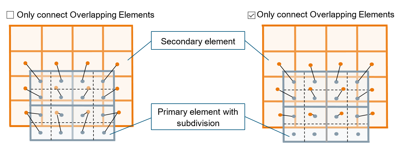
Conductances are formed based on proximity. Each primary sub-element is connected to the closest secondary element. The connection is created based only on the distance between the elements. |
Only the primary sub-elements that overlap are connected to the secondary elements, and the remaining primary sub elements that do not overlap do not form conductances. |
Understanding overlap projection direction with element subdivision method
When you select the Only Connect Overlaping Elements option, an overlap test between each sub-element of the primary elements and the elements of the secondary elements is performed. You can choose which normal is used to check for overlapping elements.
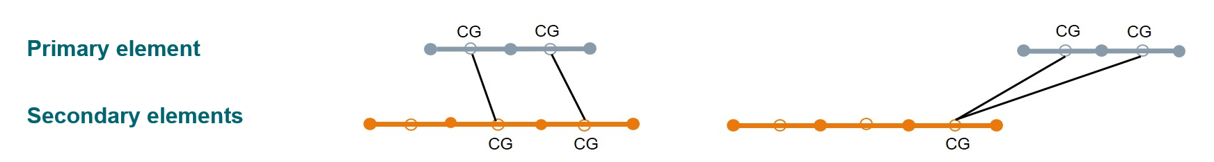
The following example illustrates the effect of using secondary element normals.
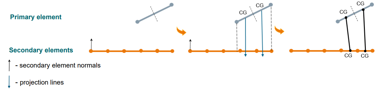
The overlap test is done by projecting the primary element onto the secondary element. Projection lines are parallel to the secondary normal. Overlap exists when the line intersects the secondary element. Two subdivisions of the primary element are found to overlap two secondary elements, therefore, both are connected. The overlapping area is the area of the two primary element subdivisions.
The following example illustrates the effect of using the primary element normals.
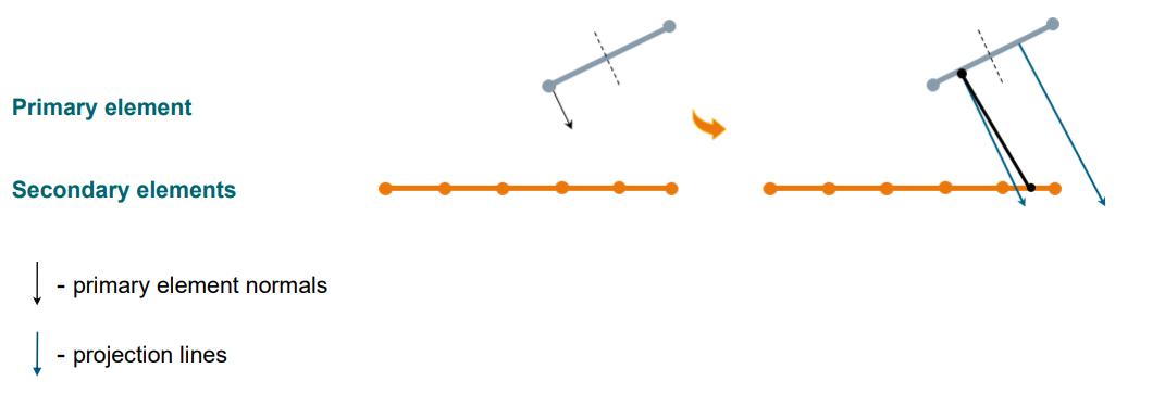
Only one subdivision of the primary element is found to overlap two secondary elements, however, only one element is connected. Therefore overlapping area is the area of the first primary element subdivision.
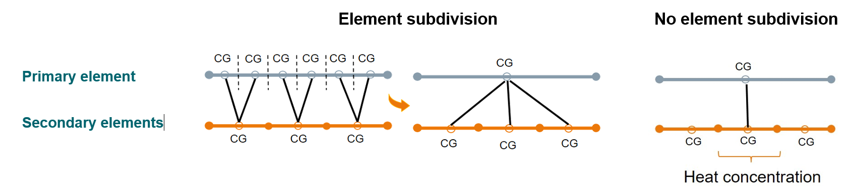
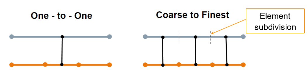
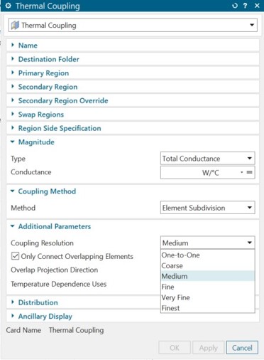
Controlling coupling resolution
You can specify the coupling resolution that controls the primary element subdivision and the conductances generated.
|
|
False heat concentration occurs when you specify a large primary element coupled to a single small secondary element.
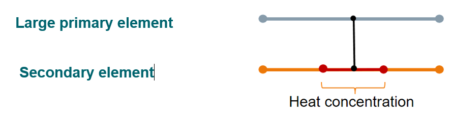
To smoothly distribute conductances, the primary and secondary mesh sizes should be roughly the same, within a ratio of one to five.
Understanding the projective intersection method
This method connects primary elements to secondary elements that overlap along a given projection direction. It computes the exact overlap area between the two sets of elements. The projective intersection method generally provides more precise coupling calculations than the element subdivision method. However, in some cases, it generates different coupling results, which depend on the projection direction.
The following elements are supported by projective intersection method: 0D, 1D, 2D elements, edges of 2D elements, and faces of 3D elements.
- Elements with edge coatings of null shells, which do not have thicknesses, and non-geometric elements.
- Axisymmetric elements.
Understanding the overlap projection direction with the projective intersection method
When you choose the overlap projection direction, make sure that the elements of the selected region (primary or secondary) do not auto-overlap when projected onto a 2D plane perpendicular to the selected direction.
- Using primary elements normal
-
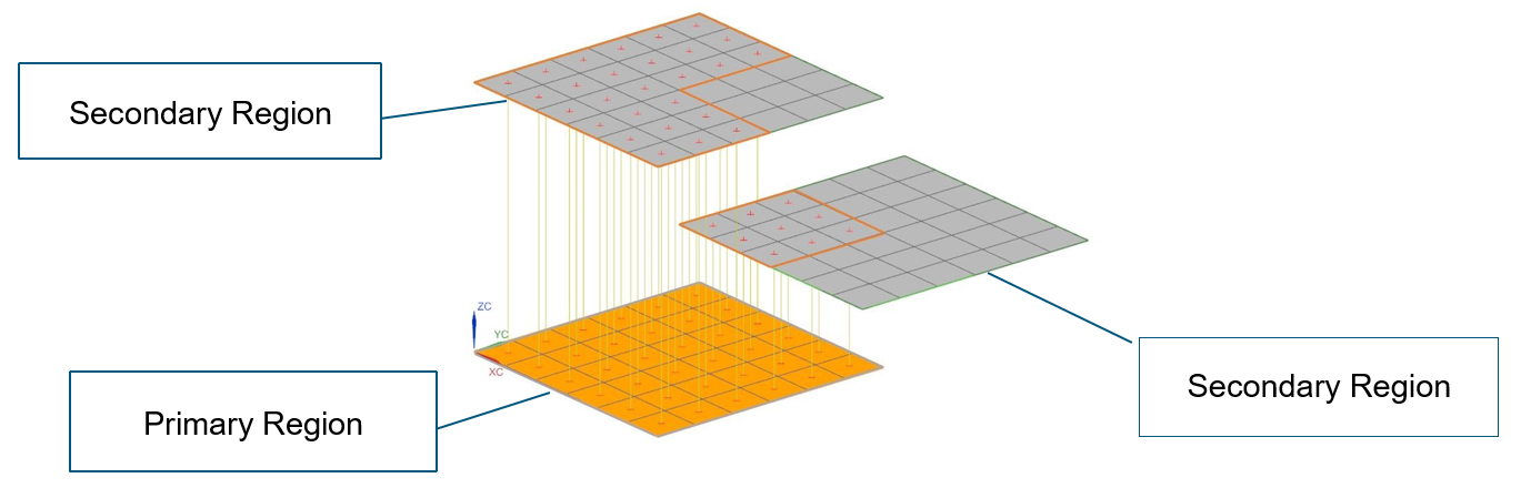
Each secondary element (grey) is projected to the primary elements (orange). When multiple secondary elements overlap the same primary element, the distance of projection is considered. A secondary element may hide another secondary element and prevent it from coupling to a primary element, partially or completely.
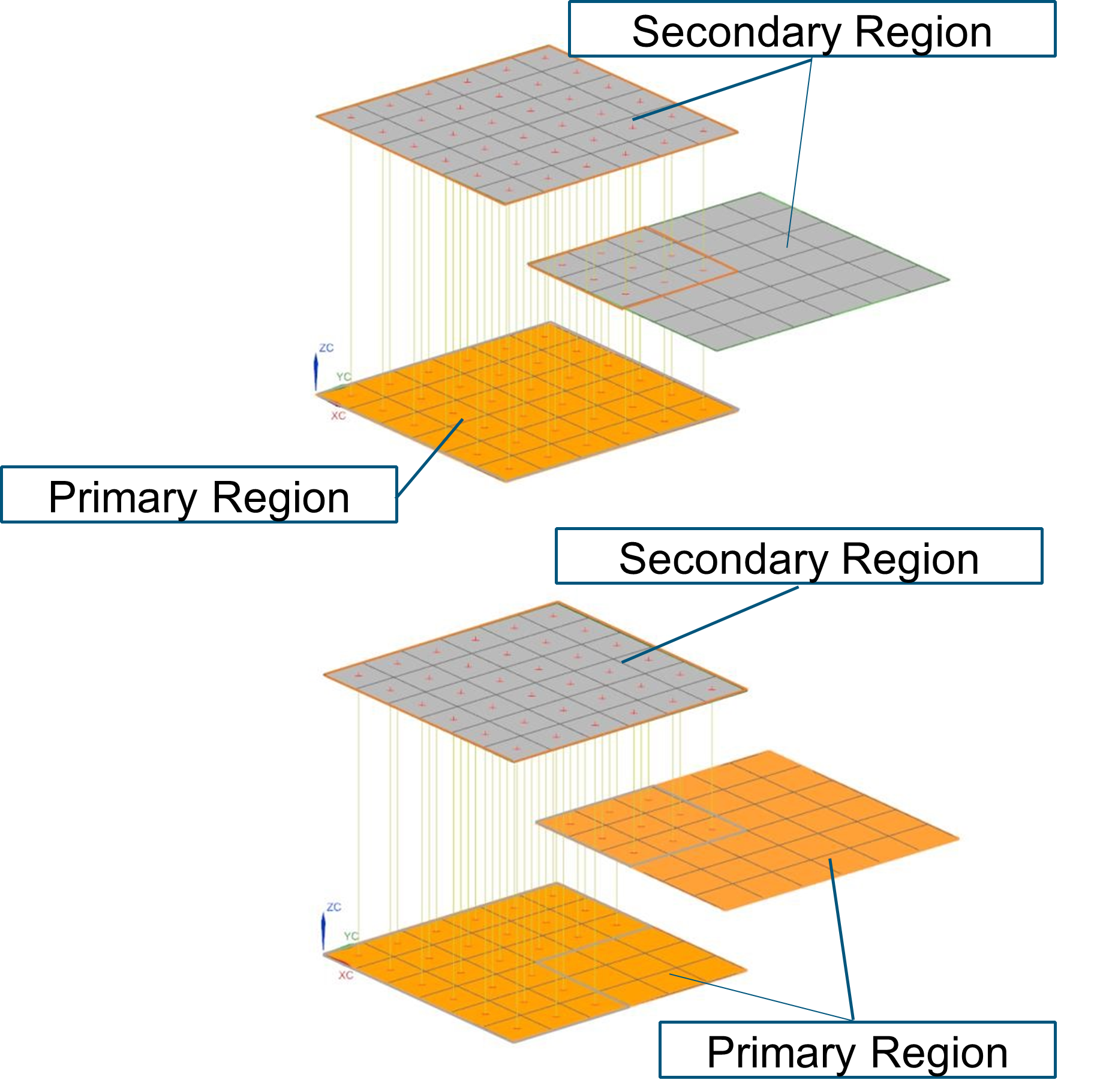
- Using secondary elements normal
-
When the secondary element normals are used to project, each primary element is projected on to the secondary elements. Because each secondary element is processed individually to determine which primary element can be projected onto it, multiple secondary elements can be connected to the same primary element. If you select different primary and secondary regions such that the primary region contains elements from the bottom and middle planes, and the secondary region contains only top elements, different elements are connected, but elements cannot connect twice.
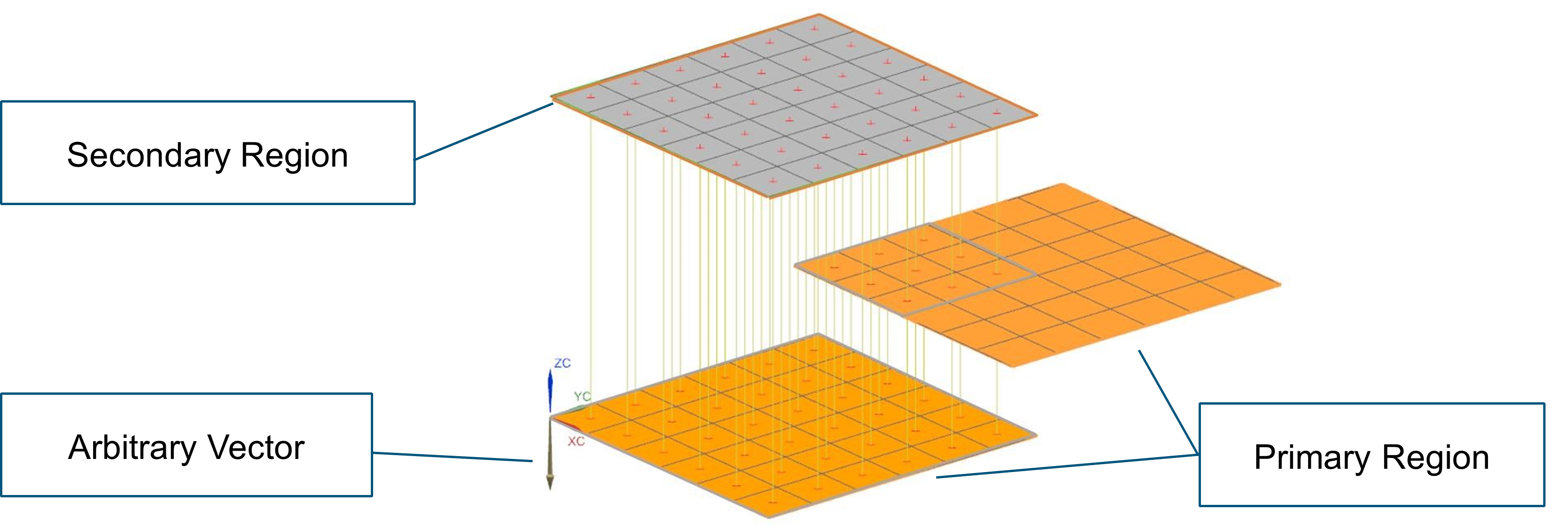
- Using user specified direction
-
When you specify an arbitrary vector for the overlap projection direction, each secondary element is projected to the primary elements using the specified vector. In this case, elements are connected twice if the elements in the primary region overlap other elements also in the primary region when projected onto a 2D plane perpendicular to the specified vector, as shown in the following image.
Visualizing thermal coupling connections while setting up the solution
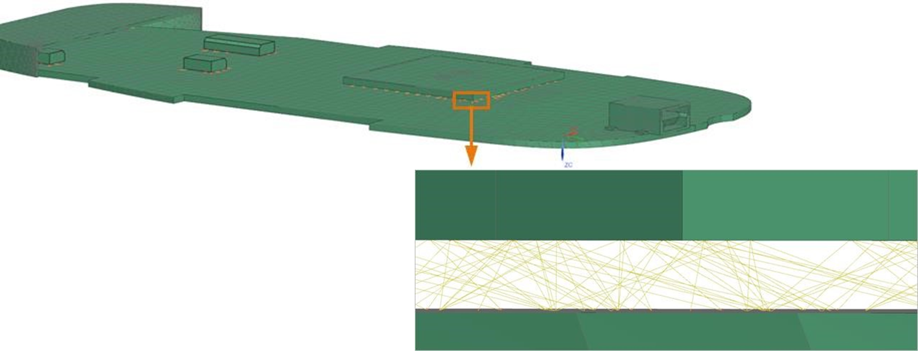
Use the Ancillary Display option to preview the connections between primary and secondary elements of one or more basic thermal couplings when the coupling method is a projective intersection.
The ancillary display supports thermal couplings of 0D, 1D, and 2D elements, edges of 2D elements, and faces of 3D elements when they can infer an area for each type.
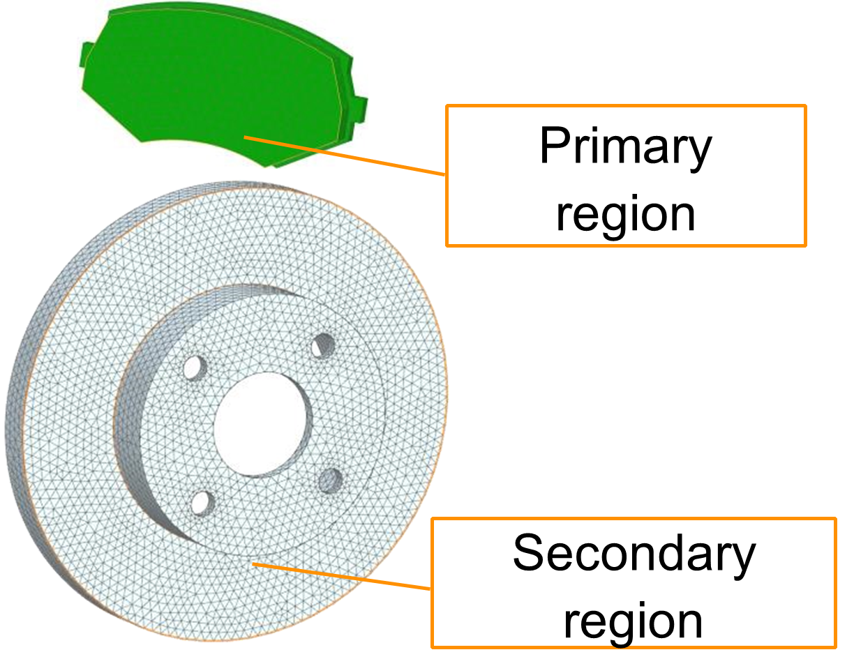
Selecting the primary and secondary regions
- Select the smaller segment as a primary region.
- Select the coarse mesh as a primary and fine mesh as a secondary region.
- Note that the primary element selection does not control the direction of heat flow. Whether you select one region as a primary or the other, it does not mean that the flow will flow from the primary to secondary region. The heat flow will follow the direction it needs to go.