How to constrain duct temperatures on nodes or elements in Simcenter 3D?
Learn how to constrain duct temperatures on nodes or elements in a simulation, ensuring accurate thermal results when modeling convection coupling and heat exchange in constrained ducts.
Overview
The way the duct is constrained impacts the temperature results when modeling convection coupling between the duct and the convecting solid region. In general, there are two types of thermal coupling convection boundary conditions that are mostly used to model convection between ducts and solid regions: Convection Coupling and Duct Node Convection Coupling.
Modeling convection on constrained duct elements
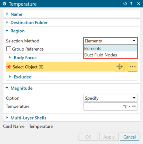
When you define the duct temperature by selecting the curve of the duct and setting the Selection Method to Elements, the thermal solver constrains only the 1D elements of the duct. If you use the Duct Node Convection Coupling type of the Thermal Coupling - Convection simulation object on the same duct, the thermal solver computes convective heat exchange between duct nodes and the convective region on the wall. Since the temperature is not imposed on nodes, temperature nodal results may fluctuate on duct nodes, but temperature elemental results will match the temperature constraint. However, if you use the Convection Coupling type, the temperature results will be consistent across both nodes and elements.
Modeling convection on constrained duct nodes
When you use the Convection Coupling type of the Thermal Coupling - Convection simulation object, the thermal solver computes convective heat exchange between fluid duct elements and the convective region on the wall. If you define the duct temperature only on the duct nodes by selecting Duct Fluid Nodes from the Selection Method list, temperature elemental results may fluctuate since the temperature is not imposed on elements, but temperature nodal results will match the temperature constraint. However, if you use the Duct Node Convection Coupling type, the temperature results will be consistent across both nodes and elements.
Modeling heat exchange with Immersed Ducts
You can use the Immersed Ducts simulation object to model the convection between the created 1D duct network, which represents cooling hole passages, and surrounding 3D solid elements without explicitly modeling the holes in 3D geometry such as blades or vanes. Each element of a 1D duct automatically couples to a 3D solid element.
When modeling the heat exchange between ducts and surrounding elements using the Immersed Ducts simulation object, the thermal solver computes the heat exchange on 1D duct elements, while nodes are used for advection propagation of heat along the duct. To fully constrain the model, apply the duct temperature to both nodes and elements. This must be done using two different Temperature constraints. This will maintain consistency in temperature results across nodes and elements, preventing fluctuations.