Clearance analysis
This topic explains how WEM predicts transient axial and radial clearances, evaluates rotor-to-casing interactions, and supports clearance optimization, leakage assessment, and rotor-rub risk analysis in gas turbines.
This lesson may include hands-on exercises. Review the Discussion section for background information or click the button to proceed to the practical section.
Discussion
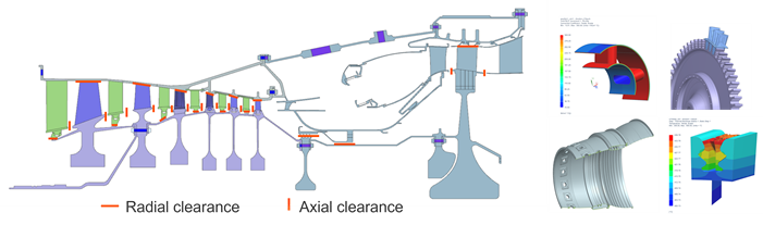
One of the primary purposes of a WEM is to calculate clearances throughout the engine, including blade tips, labyrinth seals, rim cavities, and axial gaps in the flow path, to predict performance, improve efficiency, and identify potential contact between parts.
Axial and radial clearances are calculated at various locations in the engine. Conical or angled blade tips require consideration of both axial and radial displacements. You must estimate or calculate 3D effects.
- Transient tip clearances
- Linear thermal expansion describes how a component expands or contracts as
temperature changes:
Where:
- is the dimensional change.
- is the coefficient of thermal expansion.
- is the original length.
- is the temperature change.
As the engine accelerates, decelerates, heats up, or cools down, both the rotor and casing experience thermal and mechanical deformation. These changes continuously modify the clearance between components.
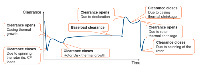
Hot running clearance is defined as the difference between the baseload clearance and the minimum clearance during the cycle. The minimum clearance is then used to determine the cold build clearance.
In a hot restart, the rotor remains warmer than the casing, so the engine starts at minimum clearance. This condition is more critical than a cold start.
- Clearance effects on the SAS model
- Transient clearance changes in the Whole Engine Model (WEM) directly affect
the behavior of the Secondary Air System (SAS).
As rotor and casing clearances vary during the mission profile:
- The WEM predicts transient clearance changes caused by thermal expansion and rotor growth.
- Labyrinth seal leakage and purge-flow mass flow rates change as the seal clearances open or close.
- Available cooling flow supplied to turbine blades and other components changes accordingly.
- Calculating tip clearance
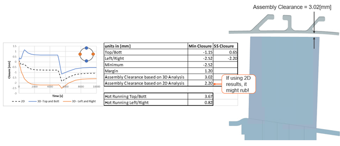
- The classical approach uses 2D WEM results to estimate transient tip
clearance and define assembly clearances with additional safety margins.
However, 2D models cannot fully capture:
- Circumferential thermal gradients.
- Local structural deformation.
- Asymmetric casing behavior.
- Nonuniform rotor expansion.
As a result, 2D-based clearance predictions may require conservative safety margins.
3D clearance analysis provides improved accuracy by accounting for local thermal and structural behavior around the engine circumference.
A potential design modification is to use adjustable vane carriers or ring segments to vary assembly tip clearances around the circumference of the engine.
- Calculating tip clearance - Design modifications
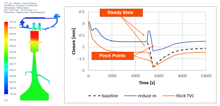
- Transient tip-clearance analysis helps engineers evaluate how design
modifications affect rotor-to-casing clearance throughout the engine
operating cycle.
Different design configurations can significantly change:
- Steady-state clearance levels.
- Pinch points are operating conditions where the clearance reaches a minimum value.
- Clearance recovery during cooldown.
- Rotor rub risk.
Hands-on material
To gain experience with the topics discussed here, complete the following: