Thermal results extraction
This topic explains how to use thermal results from a 2D WEM as boundary conditions for detailed 3D thermal and structural component analyses.
This lesson may include hands-on exercises. Review the Discussion section for background information or click the button to proceed to the practical section.
Discussion
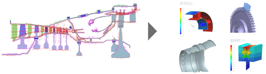
A common workflow in gas turbine development is to create detailed 3D component submodels that use temperature results from the 2D WEM as thermal input conditions.
This approach is useful when components:
- Exhibit asymmetric thermal behavior.
- Include non-axisymmetric geometric features.
- Require design-life calculations such as LCF, HCF, or creep analysis that are not performed directly in the WEM.
There are two approaches in this workflow:
- Mapping material temperatures directly.
- Mapping convective boundary conditions such as fluid temperature and HTC.
Mapping convective boundary conditions enables designers to calculate more realistic thermal gradients and ultimately achieve higher accuracy in their design-life calculations.
Hands-on material
To gain experience with the topics discussed here, complete the following: