Investigate and resolve thermal stream flow reversal warnings
You will investigate the warnings and troubleshoot your model.
Open the Simulation file
Open the part file and reset the dialog box settings.
-
Click OK.
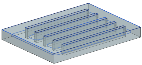
The geometry represents a section of a heat exchanger. The flow inside the heat exchanger is modeled using duct elements. The duct is made of a 1 mm thick aluminum shell. The water inside the heat exchanger moves at a low flow rate of 1 l/min and the channels are exposed to air.
Modify the solution and solver parameters
The solution is already setup with several boundary conditions. You will modify some solution and solver parameters.
- In the Simulation Navigator, right-click the Solution 1 node and choose Edit to observe the solution parameters.
- On the Initial Condition page, set the Thermal Initial Temperature to Uniform to set specified uniform temperature value.
- Click OK.
- In the Simulation Navigator, right-click the Solution 1 node and choose Edit Solver Parameters.
- On the General tab, set the Scratch Directory to Simulation-Solution Name to generate a subdirectory in the working directory with the name of the current simulation followed by a hyphen and the name of the active solution.
- Click OK.
- Expand the Solution 1→Simulation Objects, Constraints, and Loads nodes to explore the existing boundary conditions.
Solve the model
Solve the model and inspect the solution messages.
-
Review the messages in the Solution Monitor.
Toward the end, you can see a fatal error.
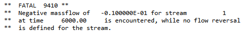
The solve ended with an error.
Modify the thermal stream load
Investigate the cause of the fatal error that the solver reports on the thermal stream load. You can specify a reversal threshold value for the mass flow of a thermal stream with no flow reversal condition specified. When the mass flow becomes negative and its absolute value reaches the threshold, the thermal solver issues a fatal error and stops the ongoing solution. When the absolute value of the negative mass flow is below the threshold, the thermal solver substitutes the negative mass flow value with the absolute value. This lets the solution proceed for a very small mass flow value that is close to zero and accounts for numerical round-up errors. You will specify the threshold value using an advanced parameter.
-
Choose Home tab→Loads and
Conditions group→Simulation Object
Type→Advanced Controls
 .
.
-
In the Parameter Definition group, click
Catalog
 .
.
Solve the model with modified mass flow reversal threshold
Solve the model and inspect the solution massages.
-
Review the messages in the Solution Monitor.
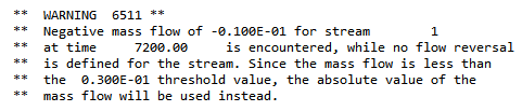
Toward the end, you can see a warning message.
Specify flow reversal condition
Specify flow reversal condition for the thermal stream load. You define inlet conditions for the reversal of the flow, and specify the values for mass flow and inlet temperature for the opposite boundary of the stream.
Solve the model with specified flow reversal condition
Solve the model and inspect the solution messages.