FEM model verification
This topic explains how to verify FEM quality, material definitions, mesh integrity, and element properties before solving a thermal model.
This lesson may include hands-on exercises. Review the Discussion section for background information or click the button to proceed to the practical section.
Discussion
Finite element model (FEM) verification ensures that the thermal model accurately represents the physical system before the solution is run. Errors in units, material properties, mesh quality, geometry connectivity, or element definitions can affect solution accuracy and lead to convergence difficulties.
- Verifying units
- Thermal solutions are highly sensitive to unit consistency.
To verify units:
- Check solution units in the Solution Units group.
- Review expressions for unit consistency.
- Select the List Expression and Units Inconsistency Warnings customer default to display the warning when inconsistent units are used.
- Verify unit capitalization using the Units Manager.
- Use the Plot Contours command to verify the units used in the boundary conditions. This applies to non-solver evaluated boundary condition definitions.
- Reviewing materials
- Incorrect material properties are a common source of thermal analysis
errors.
To avoid the errors:
- Check the Material Library source and verify that thermal properties such as thermal conductivity, specific heat, and density are defined where required.
- Add columns in the Manage Materials dialog box for quicker visualization of important thermal properties such as ρ, k, and Cp by right-clicking any column heading and selecting Columns → Configure.
- Check density and conductivity overrides applied to surfaces and solids.
- Use the Material Information command to inspect the material properties assigned to selected elements.
- Verifying mesh quality
- Thermal solution accuracy depends strongly on mesh quality and mesh
density.
Recommended practices include:
- Start with a coarse mesh.
- Refine regions with high thermal gradients.
- Minimize element distortion by avoiding highly stretched, skewed, or warped elements.
- Use mesh controls in critical regions.
- Using finite element model checks
- Use the finite element model check commands such as Element
Quality, to:
- Perform an element quality check with the following values for the
thermal solver.
Elements Interior angle, α Warp angle, β Thermal elements 1°<α<179° β<15° - Ensure the quality and consistency of your mesh.
- Validate that the model is complete and ready to solve.
- Perform an element quality check with the following values for the
thermal solver.
- Checking element normals
- All 2D elements contain top and bottom surface definitions based on their element normals.
Consistent element normals are important for defining:
- Contact between surfaces.
- Top and bottom in the radiation request.
Use the Element Normals command to:
- Display normals.
- Reverse normals.
- Automatically align normals.
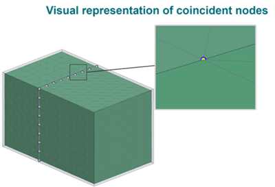
- Identifying coincident nodes
- Check for coincident nodes which are duplicate nodes lying on top of each other.
If you try to solve a model that contains coincident nodes, singularities or other rigid body motion errors can occur during the solution. Modeling conduction requires you to create meshes with shared nodes to preserve continuity.
To avoid, check, or resolve duplicate node issues, use the Mesh Mating Conditions or Duplicate Nodes commands.
- Conducting geometry checks
- Use the Element Edges command to identify free,
unconnected edges in a 2D mesh. A free edge is an edge referenced by only
one element.
To repair free edges:
- Use the Stitch Edge command to stitch disconnected edges automatically or manually.
- Repair the underlying geometry in the Modeling application if the model contains many problematic edges or fails to mesh.
- Use manual node and element operations to repair localized mesh issues.
You can also increase meshing tolerances to improve connectivity. However, excessively large tolerances may create unintended connections or introduce mesh-quality issues elsewhere in the model.
In the Model Display dialog box, enable Display Free Edges to highlight all free edges and identify regions that must be stitched before meshing.
Use the Mesh Mating command to
- Modify polygon body geometry so that surfaces share a common definition.
- Enforce common surface meshes where polygon bodies mate.
Display the material orientation of 2D or 3D elements in your model using the Element Material Orientation command.
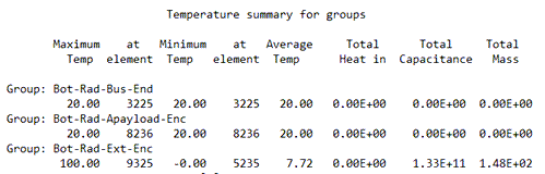
- Assessing mass properties
- Use the Solid Properties right-click command to
verify the model’s surface area and mass. The surface area is used for
convection and radiation calculations, and the model mass multiplied by its
specific heat defines the thermal capacitance.
Ensure that materials with very low thermal capacitance, such as MLI, do not have mass assigned. This can cause convergence issues at solve time.
Inspect the [Solution_name]_report.log file that contains calculation details, model parameters, elements that the thermal solver created, and group summaries.
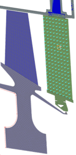
- Verifying element thicknesses
- You can use:
- Plot Thickness Contours to generate a contour plot of shell element thicknesses as a standard post view.
- Thickness Information to create a color-coded line display that shows the general statistical distribution of the thickness values across your 2D mesh.
You can use the thickness display to quickly identify:
- Any sudden changes in color that may indicate incorrectly assigned thickness values.
- Elements that do not have an assigned thickness.
Hands-on material
To gain experience with the topics discussed here, complete the following: