Simulation setup checklist
This topic explains how to validate thermal boundary conditions, thermal couplings, and solution setup before running the thermal solver.
This lesson may include hands-on exercises. Review the Discussion section for background information or click the button to proceed to the practical section.
Discussion
Before solving the model, review the simulation setup to confirm that all boundary conditions and thermal connections are correctly defined.
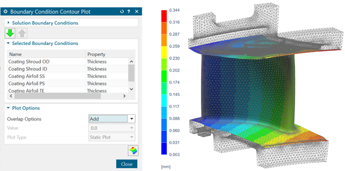
- Generating plot contours of boundary conditions
- Use the Boundary Condition Contour Plot command to
generate contour plots for most loads, constraints, and solver-specific
simulation objects that contain numerical values.
You can use these contour plots to:
- Verify your loading conditions.
- Generate high-quality visualizations for reports.
- Interrogate and extract loading data.
In this example, the thickness field varies spatially. The coating is thicker at the leading edge and gets thinner toward the trailing edge.
- Verifying expressions
- Use expressions to define shared parameters for the entire analysis across
multiple Simulation and FEM files.
You can:
- Press Ctrl+E to access expressions in tabular format.
- Update expressions from external files.
- Link expressions to Excel.
- Use Parameter Tables to manage multiple expressions simultaneously.
To enable warnings for inconsistent units in mathematical functions: File →Utilities →Customer Defaults →Pre/Post →Expressions →General tab, select the Warn about Inconsistent Units within Mathematical Functions check box.
- Checking radiation enclosures
- Radiation accuracy depends on properly defined enclosures and accurate view
factors.
Recommended checks include:
- Verify internal and external enclosures.
- Run a radiation-only solution to verify the setup.
- Inspect the View Factors Sum result set.
In an enclosure, the sum of any element's view factors should be equal to 1. You can control the precision of this calculation with the options in the Radiation dialog box.
- Increase radiation calculation accuracy using higher element subdivision, hemicube rendering, or additional rays.
- Resolving ID conflicts
- To resolve AFM label conflicts, right-click the active assembly FEM file →
Assembly Checks → Assembly Label
Manager.
To resolve the simulation label conflicts, right-click the active Simulation file → Simulation Label Manager.
- Verifying thermal couplings
- Thermal couplings must represent physically meaningful heat-transfer
paths.
Recommended practices include:
- Select the smaller region as the primary region.
- Select the coarse mesh as the primary and the fine mesh as the secondary region.
- Verify thermal coupling values.
- Visualize thermal connections using the Ancillary Display option when using the projective intersection coupling method before solving the model.
- Review warning messages in the log file.
- Verify and determine individual conductances of elements in a thermal coupling by inspecting scratch files. Use the FILES MODLCF, VUFF, MODLF IN ASCII advanced parameter to write intermediate files in ASCII format.
Note:Primary element selection does not control the direction of heat flow.Use the Report command to investigate heat flow between components in the assembly and from each component to the environment.
This helps you identify areas with significant heat, allowing you to determine where thermal tapes or thermal standoffs would be most beneficial in the design. The data from reports is generated in both .html and CSV formats.
If perfect-contact thermal couplings create convergence difficulties, replace them with Thermal Coupling definitions using a high heat-transfer coefficient to approximate perfect thermal contact between nonmatching meshes.
- Best practices
- Recommended best practices include:
- Add descriptions to boundary conditions.
- Keep formulas used for conductance calculations.
- Use descriptive names for solutions and simulation objects.
- Remove unused materials and modeling objects.
- Organize thermal couplings clearly.
- Validate the model incrementally throughout setup.
Hands-on material
To gain experience with the topics discussed here, complete the following: