How do I create thermal connections for axisymmetric models with bolts and nuts?
This article explains how to accurately model thermal contacts with bolts and nuts in
turbomachinery models.
Introduction
You can model heat paths between 2D axisymmetric and plane stress elements using the
Edge-to-Edge Gluing/Contact or
Surface-to-Surface Gluing/Contact simulation objects.
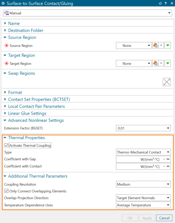
Surface-to-Surface Contact/Gluing can be used between 2D
and 3D elements, for example the face of a plane stress to the face of a 3d body.
Use these simulation objects in the coupled thermal-structural analysis to apply
both structural and thermal couplings between two regions without creating a
separate simulation object for each coupling. You activate the thermal coupling when
selecting the Activate Thermal Coupling check box.When you
create thermal couplings, select a smaller surface as a primary region.
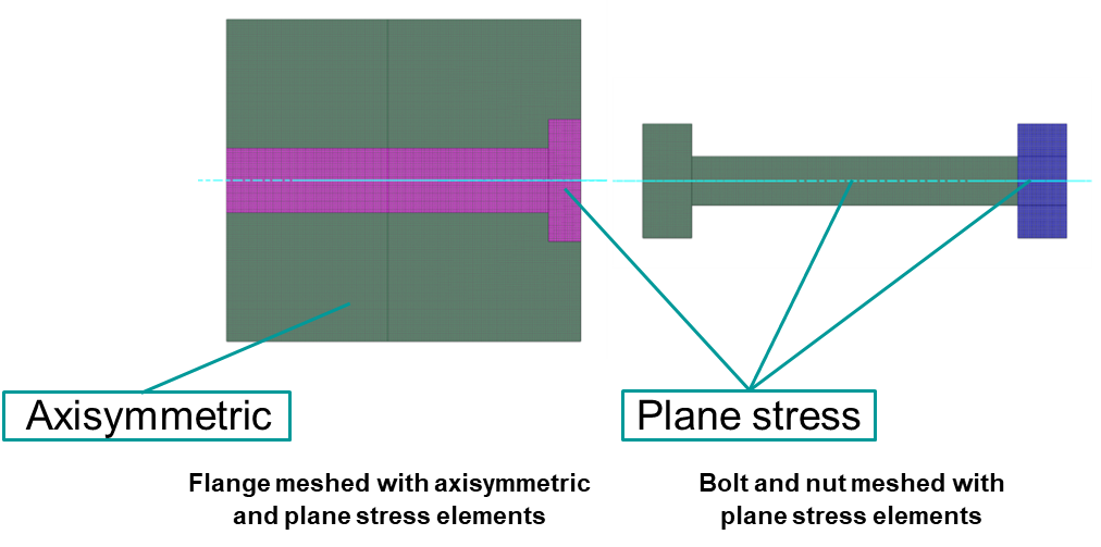
Modeling thermal contacts of the bolt and flange
To model the thermal coupling between the flange and bolt, you must define one edge
and one face coupling in the 2D model. Note that the flange is meshed using
axisymmetric elements and plane stress elements with associated hole thickness. Bolt
and nut are meshed with plane stress elements.
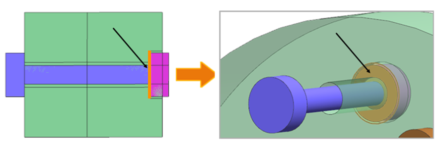
Edge coupling between the flange and bolt head
The contact area is the minimum thickness between the involved
elements.
The area of the bolt head is defined as:
The flange area is defined
as:
The area of
the flange meshed with axisymmetric element is defined as:
The area
of the flange meshed with plane stress elements is defined as:
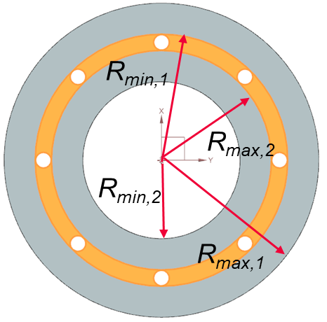
Where:
is the
external radius of the bolt.
is the
internal radius of the bolt.
is the
radius of the plane stress elements with associated hole
thickness.
is the number of
hole or bolt instances.
and
are
the maximum and minimum radius from the axis of rotation of the
first part of the flange.
and
are
the maximum and minimum radius from the axis of rotation of the
second part of the flange.
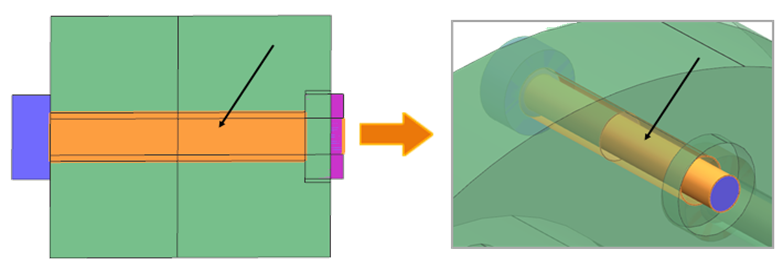
Face coupling between the flange meshed with plane stress elements and bolt
shank
For the plane stress elements of type hole and bolt, the thermal
solver considers the coupling area as the surface area of a cylinder. The
convective area is the overlapping area of the primary selection.
When the
flange (plane stress) is the primary selection:
When the bolt shank is the primary
selection:
Modeling thermal contacts of the nut and flange
To model the thermal coupling between the flange and nut, you must define one edge
and one face coupling in the 2D model:
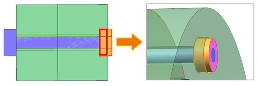
Edge coupling between the nut and flange
Face coupling between the nut and flange
The coupling area is the overlapping area of the primary selection
between the nut meshed with plane stress elements, and flange meshed
with plane stress elements defined with associated hole thickness.
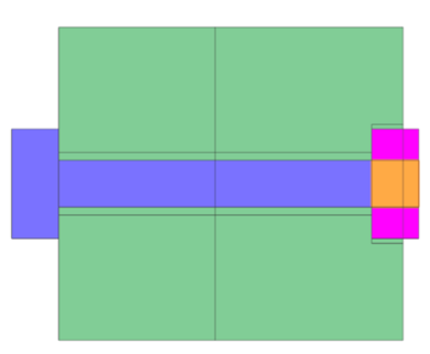
Modeling thermal contacts of the nut and bolt shank
For the nut meshed with plane stress elements defined with field or expression, the
thermal solver considers the coupling area as the surface area of a plane.
When the nut face is a primary selection:
When the bolt shank face is a primary selection:
Where:
is the length of the
nut.
is the width of the
nut.
is the number of nut
instances.
is the radius
of the bolt shank.
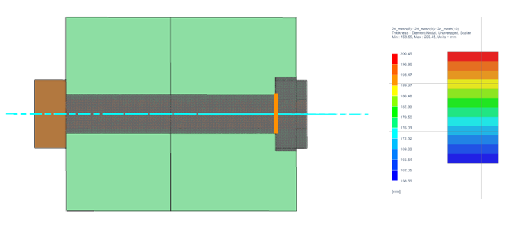
Algorithm for 2D elements edges selection
For 2D elements with the thickness, the thermal solver computes the coupling area by:
Extracting the thickness per element.
Comparing the connected elements and identifying the smallest overlap
thickness.
Multiplying by overlap length (if the overlap area option is selected) to obtain
the overlap area on the edge of each primary element.
Summing all the areas.
Calculating convective area on the internal edge
When modeling the thermal connection between the flange, which meshed with plane
stress elements and bolt head, or the nut, there is an internal edge.
To compute the coupling area, the thermal solver:
Extracts the thickness on left side () and right side () of each element of the internal edge.
Associates the thickness to each ( ) element's length .
Finds the internal line area as:
Computes the sum of convective areas as min ()
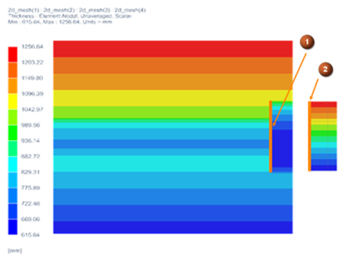
You should pay attention when modeling the thermal coupling between the flange (plane
stress) and nut, where the thickness of one of the regions is defined as an
expression or field.
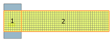
The following example shows the thickness distribution on the flange and nut edges.
The internal edge of the flange (1) exhibits decreasing thickness towards the
centerline, while the nut's thickness (2) is modeled as being proportional to its
radius.
As a result, the convective area in this thermal coupling is affected by both the nut
and the flange edges. Representing the nut in a 2D format may result in loss of
thickness distribution information, which may lead to inaccuracies in the convective
coupling. Therefore, it is recommended to use the area correction factor when
defining the heat transfer coefficient as an expression. To find the correction
factor, use the BC data summary in HTML or in table format to acquire information
about the computed convective area.
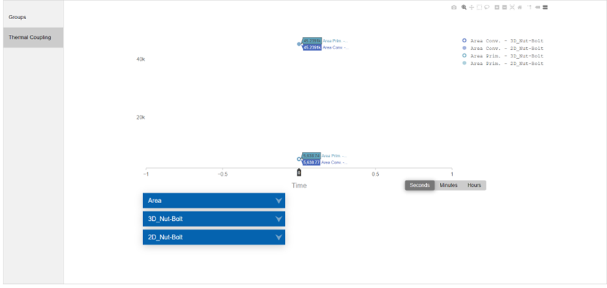
Use the PLOT BC SUMMARY advanced parameter in the solution to
generate the HTML file that displays graphs of thermal properties of thermal
couplings included in the solution.
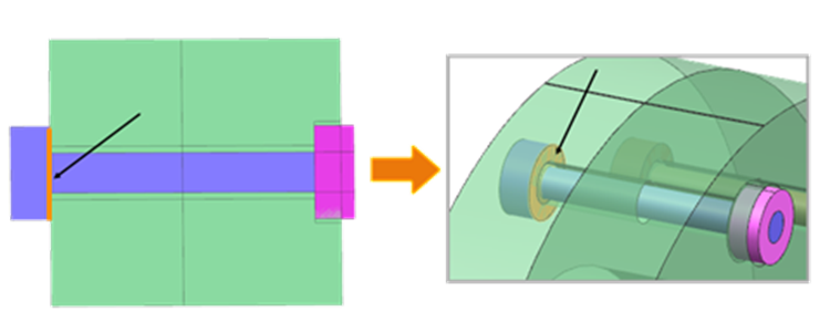
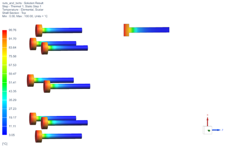
The following example shows comparison of convective areas for the 3D and 2D models
with nut and bolt thermal coupling.
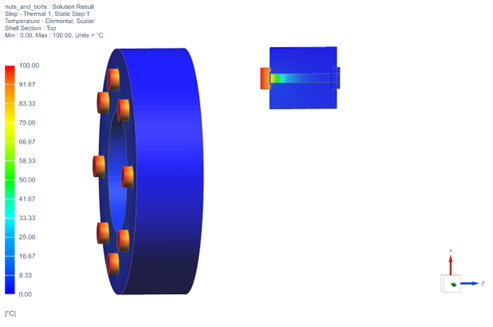
To validate the 2D model representation, compare temperature results with the 3D
model. This step helps ensure that the 2D model accurately represents the behavior
of the bolts and nuts within acceptable tolerances.
Additional recommendations
When you select the Only Connect Overlapping Elements check
box for thermal coupling:
It is recommended to divide faces so that coupled edges/faces are fully
overlapping. If the faces/edges do not fully overlap, then an overlap factor
needs to be applied to the coupling areas.
Note that the area correction will not be done by the solver for the elements
that are not used in the coupling, therefore the primary area correction may not
be as expected. In the following bolt shank and nut example, if the two surfaces
(surface 1 and surface 2) are selected as a primary area, the solver will
correct the areas based on the curvature only for the connected elements that it
detects in the thermal coupling, i.e., the surface 1. The thermal solver
considers surface 1 as a cylindrical area and surface 2 as a plane area.