How to model mixed flow from two ducts into the thermal stream?
This article shows four different approaches to model flow mixing from two ducts into the thermal stream.
Introduction
- Duct (1): mass flow = 1 kg/s, pressure = 0.1 MPa, temperature = 100°
- Duct (2): mass flow = 2 kg/s, and pressure = 0.15 MPa, temperature = 200°
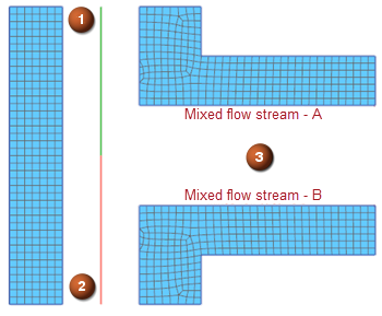
Using an expression in the thermal stream
In this method, you assign a boundary condition ID to duct elements. Then, you reference these boundary condition IDs in the thermal-flow functions to define the resulting thermal stream.
- In the Duct Flow Boundary Conditions dialog box, from the type list, select Duct Label.
- Select the first duct (1).
The software automatically assigns a boundary condition ID to the first duct.
- Using the same procedure, assign the boundary condition ID for the second duct.
- In the Thermal Stream dialog box, from the type list, select Two-Sided Stream on Edges.
- In the Path Selection -Side A group, select the edge (1)
and in the Path Selection -Side B group, select the edge
(2).
- From the Fluid Material list, select Air.
- From the Stream Conditions group, in the Mass
Flow box, type DMO(1)+DMO(2).
Functions DMO(1) and DMO(2) return the ducts mass flow for ducts with labels 1 and 2.
- In the Inlet Temperature box, type
(DMO(1)*(specfl(DTO(1)))*DTO(1)+DMO(2)*(specfl(DTO(2)))*DTO(2))/((DMO(1)+1e-8[kg/sec])*(DTO(1))+(DMO(2)+1e-8[kg/sec])*specfl(DTO(2)))
to define a mix of enthalpies from ducts for constant specific heats. where:
- is the duct's mass flow.
- is the specific heat.
- is the outlet duct temperature.
- In the Absolute Pressure box, type
(DPO(1)+DPO(2))/2.
Functions DPO(1) and DPO(2) return the outlet pressure of ducts with labels 1 and 2. The equation will prescribe the average pressure coming from both ducts.
- In the Heat Transfer Coefficient, type 0.1 W/(mm·2°C).
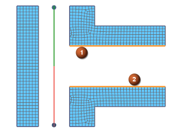
Creating mock thermal streams for each duct
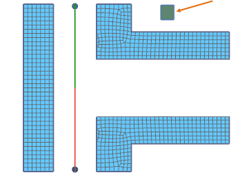
You create two mock thermal streams for each duct using DTO, DMO, DPO thermal functions. First, you must create a mock 2D mesh anywhere on the model in the FEM, as shown by the arrow in the following image. You use its edges to create the mock thermal streams for each duct.
- To create a mock thermal stream for the first duct to reference its output flow parameters, use Thermal Stream.
- From the type, select One-Sided Stream on Edges.
- In the Path Selection group, select the edge (1) of the
mock mesh.

- From the Fluid Material list, select Air.
- From the Stream Conditions, in the Mass Flow box, type DMO(1) to reference outlet duct mass flow.
- In the Inlet Temperature box, type DTO(1) to reference the outlet duct temperature.
- In the Absolute Pressure box, type DPO(1) to reference the outlet duct pressure.
- In the Heat Transfer Coefficient, type 1e-8 W/(m·2°C).
- Repeat steps 1 to 9 to create the mock stream for the duct 2 on the edge
(2).
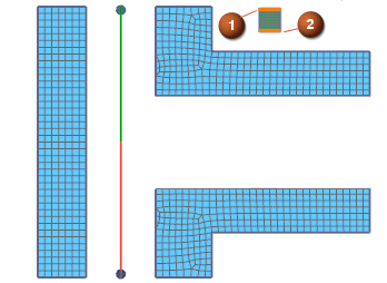
Using the MIX function
You use the MIX function to compute the resulting temperature and mass flow rate from mixing two mock streams into the resulting thermal stream.
- To create a resulting thermal stream where you mix flow from two mock thermal streams, use Thermal Stream.
- From the type, select Two-Sided Stream on Edges.
- In the Path Selection -Side A group, select the edge (1)
and in the Path Selection -Side B group, select the edge
(2).

- From the Fluid Material list, select Air.
- From the Stream Conditions, in the Mass
Flow box, type SMO(1)+SMO(2).
Functions SMO(1) and SMO(2) return the mass flow for the mock thermal streams.
- In the Inlet Temperature box, type
MIX(1,2).
Function MIX(1,2) returns the temperature from mixing two mock thermal streams.
- In the Absolute Pressure box, type
(SP(1)+SP(2))/2.
Functions SP(1) and SP(2) return the outlet pressure of mock thermal streams.
- In the Heat Transfer Coefficient, type 0.1 W/(mm·2°C).
Using the thermal stream junction
You use the Junction simulation object to mix the flow from two mock thermal streams. First, you need to create an outgoing thermal stream from the junction with a defined absolute pressure.
- To create a resulting thermal stream where you mix flow from two mock thermal streams, use Thermal Stream.
- From the type list, select Two-Sided Stream on Edges.
- In the Path Selection -Side A group, select the edge (1)
and in the Path Selection -Side B group, select the edge
(2).

- From the Fluid Material list, select Air.
- From the Stream Conditions, in the Absolute Pressure box, type (SP(1)+SP(2)/2.
- To mix the two mock thermal streams into the resulting thermal stream, use Junction.
- In the Incoming Streams group, from the Stream 1 list, select mock stream for duct 1.
- From the Stream 2 list, select mock stream for duct 2.
- In the Outgoing Streams group, from the Stream 1 list, select mixed flow stream.