How can I understand and diagnose my thermal model results and setup?
This article explains how to evaluate thermal performance and verify the setup of the model during and after the solve by generating different results data.
Introduction
To evaluate thermal performance of a model, you can display:
- The thermal and fluid properties of supported loads and simulation objects during the analysis.
- Convergence and tracked result graphs using the Solution Control Monitor to monitor the analysis during the solve and using the HTML file generated by the thermal solver to evaluate the analysis information after the solve.
- Results of the analysis after the solve, by loading the results in the Post Processing Navigator.
Displaying data summary in a graph and table
To monitor important areas of your model at run-time, you include the PLOT BC SUMMARY advanced parameter in the solution. The thermal solver generates the <simulation name>-<solution name>data.html file that displays graphs for:
- Thermal and fluid properties of the Thermal Stream, Thermal Convecting Zone, Thermal Void loads and Thermal Coupling, Immersed Duct, Heat Pipe type of Thermal Device simulation objects.
- Named points and groups of elements.
This file is updated at each time step during the solve and stored in the run or scratch directory.
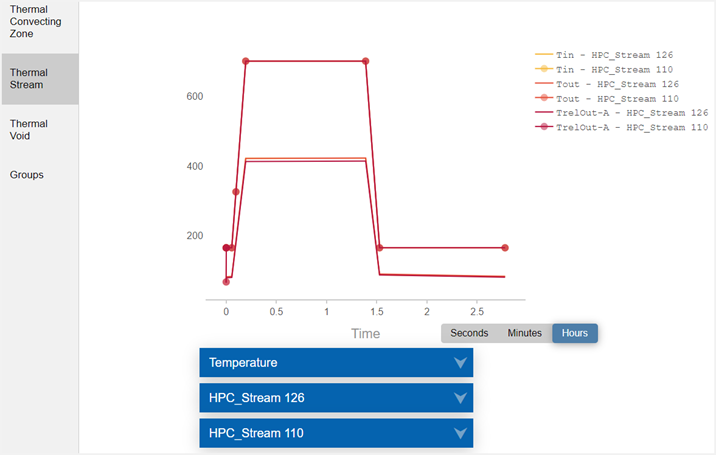
In the following example, it was requested to display how temperature varies for streams 126 and 110 during the 3 hours solve. The graph shows the streams inlet and outlet fluid temperature, as well as the outlet relative temperatures on side A of the streams.

When you include the DISPLAY BC SUMMARY TABLES advanced parameter in the solution, the thermal solver generates the <simulation name>-<solution name>.bcdata file that stores the time and evaluated boundary condition data in a table format. This file is updated at each successful time step during the solve and stored in the run or scratch directory.

Outputting the convecting area information
| Load type | Thermal-flow functions |
|---|---|
| Thermal Convecting Zone | ZA(i) |
| Thermal Stream | SA(i), SA2(i) |
| Thermal Void | VA(i) |
The output convecting areas are the values returned by the functions when you use them in expressions.

Verifying thermal convective boundary conditions set up
In a whole-engine thermomechanical analysis, fluid flow is often represented by specialized turbomachinery thermal convective boundary conditions such as thermal streams, convective zones, and voids. They are often used to model convective heat transfer in turbomachinery and rotating machinery models. The complex way these boundary conditions are interconnected makes diagnosing and tracking down model setup errors difficult. For instance, the outlet of one stream can feed one or multiple streams, or a stream can feed a void.
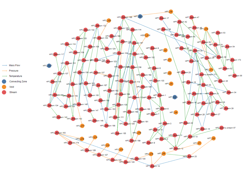
When you include the BC DEPENDENCY GRAPH advanced parameter in the solution, the thermal solver generates the BCInterdependencyGraph.html file, that contains a graph illustrating the dependencies, such as temperature or mass flow, between the thermal streams, voids, and convecting zones boundary conditions that are included in the solution. You can also display the dependencies, such as pressure, swirl velocity, heat load, area correction, and heat transfer coefficient or choose only to display the temperature or the mass flow rate dependencies, separately.
In the following example:
- The boundary conditions are represented by nodes, and they are marked by the name of the related boundary condition.
- The dependencies between the boundary conditions are represented by arrows, which show the dependency direction.

Generating solver graphs in HTML
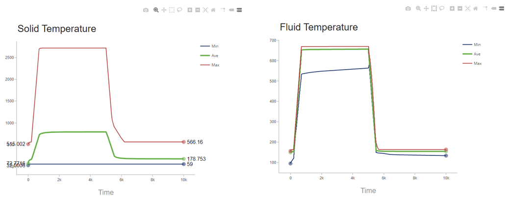
You can display convergence and tracked result graphs from the solvers, using the Solution_Monitor_Graphs.html file, which is generated after the solve ends and stored in the run or scratch directory. You can easily inspect solver graphs by magnifying a section of the plot to inspect it in more detail.

Output files
The following are the files that the solver writes during and after the solve.
Bun file
- The <simulation/model name>-<solution/analysis name>.bun is the post-processing file that contains the solver results. This file is in binary format.
Log files
- The <simulation/model name>-<solution/analysis name>.log is a log file that contains information, such as warnings and error messages, and iterative convergence data generated by the Solution Monitor during an analysis.
- The <simulation/model name>-<solution/analysis name>_report.log is a log file that contains calculation details. This file is always appended to the solution.
- The <simulation/model name>-<solution/analysis name>_verbose.log is a log file that contains messages regarding thermal solver routines, including their timing and memory statistics and verbose messages.
Error file
- The <simulation name>-<solution name>.err is an error file that identifies the error number for a solve, if applicable. An error number that is different from 0 indicates that the solve completed with a fatal error.
