Set up radiation requests
Practice set up radiation request, troubleshoot, and identify common issues encountered when modeling radiation.
Open the Simulation file
Open the Simulation file, reset the dialog box settings, and explore the model.
- Choose File→Open and open basic_radiation\basic_radiation_sim1.sim.
- Choose File→Preferences→User Interface.
- On the Dialog and Precision page, click Reset Dialog Memory.
- Click OK.
-
In the Simulation Navigator, explore the defined
boundary conditions:
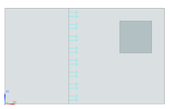
- Heat load of 10 W on the big enclosure face.
- Temperature constraint set to 25 °C on the small enclosure face.
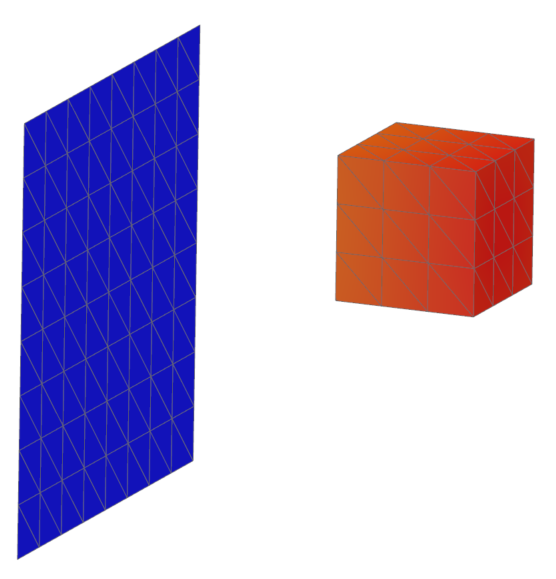
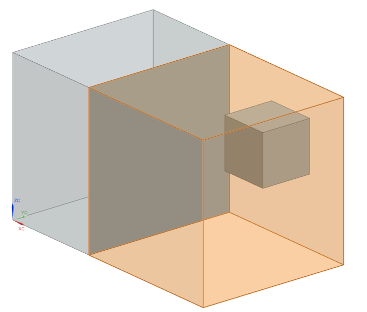
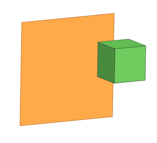
The model contains two enclosures, middle surface, and a cube inside the big enclosure.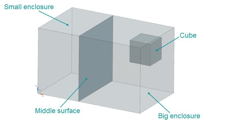
Check element normals
Verify and orient the mesh elements before running the analysis. The direction of the normals defines the top and bottom thermo-optical properties.
- In the Simulation Navigator, double-click the basic_radiation_fem1.fem node to make the FEM file active.
- In the Simulation Navigator, expand the basic_radiation_fem1.fem → 2D Collectors → Inner_shell_collector nodes, right-click the inner_shell_mesh node and choose Check → Element Normals.
-
Click Display Normals.
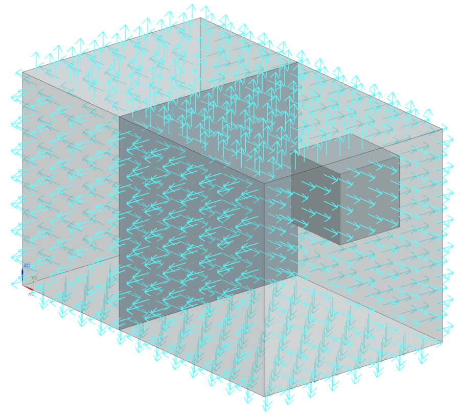
The normals are pointing outwards, you need to reverse the normals to simplify setup doing internal radiation only. - In the Method group, select Orient Normals.
- In the Simulation Navigator, under 2D Collectors, show inner_shell_mesh.
- In the graphics window, select any element from the small enclosure.
- In the Seed Element group, select the Reverse Normal check box.
- Click Align Normals.
- Repeat the steps 6-8 for the big enclosure.
- Click Close.
Merge duplicate nodes
By merging the duplicate nodes, you are ensuring that the heat will flow through the wall between the two enclosures as if they were a single object.
- In the Simulation Navigator, under the inner_shell_collector node, right-click the inner_shell_mesh node and choose Check → Duplicate Nodes.
- In the Nodes to Check group, clear the Ignore Nodes in Same Mesh check box to let the software identify nodes within the Tolerance as duplicates.
- Select Displayed from the list.
- Click Merge Nodes.
- Click Close.
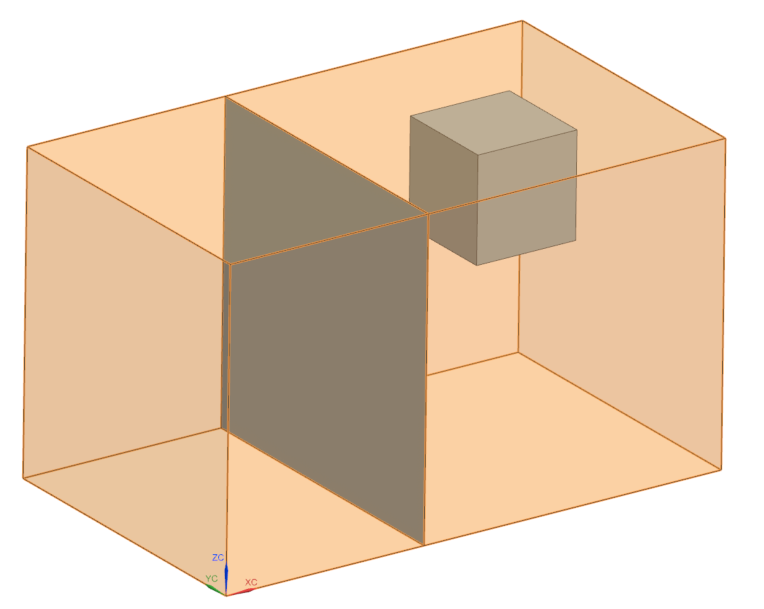
Define a radiation enclosure of the block
Define a radiation enclosure with the surfaces of the block. Radiation calculations must be done within an enclosure. You have already verified that elements are facing each other. As a result of their orientations, the elements define an enclosure. Enclosure Radiation will only calculate radiation using the selected elements.
- In the Simulation Navigator, double-click the basic_radiation_sim1.sim node to make the Simulation file active.
- Hide inner_shell_mesh.
-
Choose Home tab→Loads and
Conditions group→Simulation Object
Type list→Radiation
 .
.
- Make sure that the type is set to Enclosure Radiation.
- In the Top Border bar, from the Type Filter list, select Polygon Face.
-
In the graphics window, select 10 faces of the block.
- In the Parameters group, clear the Include Radiative Environment check box to model radiation only within enclosure.
- Make sure that the Elements not Part of this Enclosure Can Shadow check box is cleared to limit shadowing checks to those elements in the enclosure.
- Click OK.
Solve the model
- In the Simulation Navigator, right-click the Solution 1 node and choose Solve.
- Click OK.
-
If you have an Error message, click
OK and explore the
Information window.
Notice that there is a conflict with assembly or simulation label manager.
- Close the Information window.
- Cancel the solve.
- In the Simulation Navigator, right-click the basic_radiation_sim1.sim node and choose Simulation Label Manager.
-
In the Labels group, select the Modeling Objects tab.
Notice that there is a conflict indicating that this Simulation file has an offset range for its labels that overlaps with the offset range of the FEM.
-
In the Automatic Label Resolution group, click
Automatically Resolve
 to resolve node, element, and coordinate system
labels, using the specified offset type and value.
Notice that the status is valid now indicating that no label in this Simulation file conflicts with the FEM.
to resolve node, element, and coordinate system
labels, using the specified offset type and value.
Notice that the status is valid now indicating that no label in this Simulation file conflicts with the FEM. - Click OK.
- In the Simulation Navigator, right-click the Solution 1 node and choose Solve.
- Click OK.
- In the Review Results message box, click No.
- Close the Information window.
- In the Analysis Job Monitor dialog box, click Cancel.
Display results
Visualize the nodal temperature results for the enclosure. Notice that there is no restriction on the radiation paths.
- In the Simulation Navigator, expand the Solution 1 node, double-click the Results node.
-
In the Post Processing Navigator, expand the
Thermal node, double-click
Temperature-Nodal.
-
Observe that:
- Conduction is the dominant heat transfer mode in this analysis, but radiation is also being considered.
- No thermo-optical properties were defined to the bottom side of the meshes, therefore they do not see the environment and do not radiate to it.
- The cube and the middle surface are not included to the radiation calculation.
-
In the Post Processing Navigator, under the Thermal node, double-click View Factors Sum - Elemental.
Observe that the view factors sum is 1.18. In an enclosure, the sum of any element's view factors should be equal to 1. Each view factor represents a fraction of the energy an element radiates in the enclosure. Since all the energy the element radiates either reaches other elements that are inside the enclosure or escapes to the radiative environment, the sum of the fractions is 1. In this example, the view factor sum is more than 1, because of imprecision in the calculation of partial views.
-
Choose Results tab→Display
group→Cutting Plane Options
 .
.
-
In the Cut Position group, select the Apply Immediately check box.
Notice that the view factor sum on the middle surface is equal to 0, since it is not included to the radiation calculation.
- Click OK.
Modify the calculation method settings
Increase the number of rays from each element to improve the view factor sum.
-
Choose Results tab→Context
group→Return to Home
 .
.
- In the Simulation Navigator, expand the Simulation Objects node, right-click Radiation and choose Edit.
- In the Parameters group, next to Monte Carlo Settings, click Edit.
- In the Settings group, in the Number of Rays box, type 10000 to increase the number of rays to improve the element's view factors.
- Click OK in both dialog boxes.
Solve the model and display results
- In the Simulation Navigator, right-click the Solution 1 node and choose Solve.
- Click OK.
- In the Review Results message box, click No.
- Close the Information window.
- In the Analysis Job Monitor dialog box, click Cancel.
- In the Simulation Navigator, under the Solution 1 node, double-click the Results node.
-
In the Post Processing Navigator, expand the Thermal node, double-click View Factors Sum - Elemental.
Notice how the view factors sum is improved.
Include the cube to the radiation enclosure
Include the small cube in the analysis to calculate the amount of radiation emitted by the walls that is absorbed by the cube. To calculate the radiation on the cube you must include it in the enclosure you previously defined.
-
Choose Results tab→Context
group→Return to Home
.
- In the Simulation Navigator, double-click the basic_radiation_fem1.fem node to make the FEM file active.
- In the Simulation Navigator, under the 2D Collectors node, show cube_mesh.
- Right-click the cube_mesh node, and select Check → Element Normals.
- In the Method group, select Check Normals.
-
In the Elements to Check group, select Displayed.
The normals are pointing outwards.
- Click Close.
- In the Simulation Navigator, double-click the basic_radiation_sim1.sim node.
- Under the Polygon Geometry node, hide Big_enclosure, and under 2D Collectors, hide cube_mesh.
- In the Simulation Navigator, hide Simulation Object Container, expand it and right-click Radiation (1) and choose Edit.
-
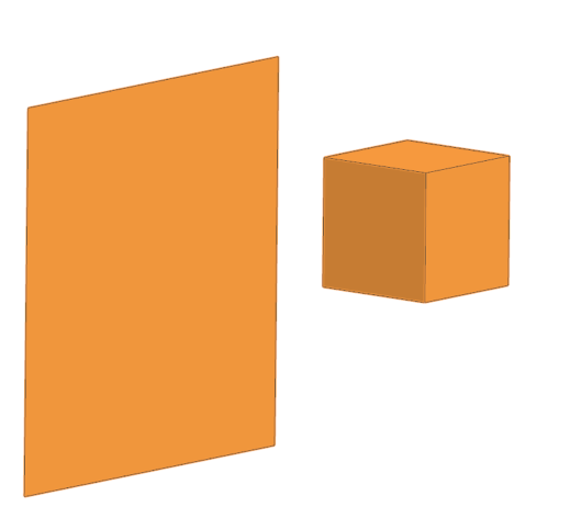
Select six faces of a small cube.
There are 16 selected faces in total.
- Click OK.
Solve the model and display results
Solve the model with the same initial enclosure but with the cube as an obstruction.
- In the Simulation Navigator, right-click the Solution 1 node and choose Solve.
- Click OK.
- Wait for Completed to display in the Analysis Job Monitor dialog box, before proceeding.
- In the Review Results dialog box, click No.
- Close the Information window.
- In the Analysis Job Monitor dialog box, click Cancel.
- In the Simulation Navigator, double-click the Results node.
- In the Post Processing Navigator, under the Thermal node, double-click Temperature-Nodal.
-
Under the Post View 4 →
basic_radiation_fem1.fem → 2D
Elements → Inner_shell_collector
node, hide inner_shell_mesh to observe the
temperature distribution on the middle surface and cube.
-
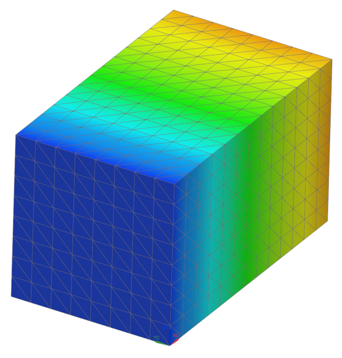
Hide middle_surface_collector to display the
temperature on the cube.
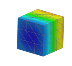
Observe that the cube:- Temperature range is 73-79 °C.
- Is heated up through radiation.
- Has no conduction to the temperature sink or the heat source.
- Is being radiated by its surrounding meshes.
Include the middle surface into the radiation enclosure
Include the middle surface into the radiation enclosure. In most thermal models, some elements radiate differently from each side. Top and bottom radiation values must be defined.
-
Choose Results tab→Context
group→Return to Home
.
- In the Simulation Navigator, double-click the basic_radiation_fem1.fem node.
- Under the Polygon Geometry node, show Big_enclosure.
- Expand the middle_surface_collector node, right-click the middle_surface_mesh node, and select Check → Element Normals.
-
Click Display Normals.
Tip: To view your model as displayed, you can press Ctrl+Alt+F to orient your model with the Front view or select Front from the Orient View Drop-down list in the View toolbar.
The normals must point towards the cube. - Click Close.
- In the Simulation Navigator, double-click the basic_radiation_sim1.sim node.
- Right-click the Radiation node and choose Edit.
-
In the graphics window, select the middle surface.
Tip: Hide the Big_enclosure and Small_enclosure geometry. There are 17 selected surfaces for the top region.
-
In the Bottom Side Region group, click Select Object and select the middle surface.
By including the middle surface in the bottom side region, you make it radiate from the bottom. If you include the middle surface only in the top side region, radiation coming from the back passes through it.
- Click OK.
Solve a modified solution and display results
Solve the model considering the original enclosure of the cube and the section surface.
- In the Simulation Navigator, right-click the Solution 1 node and choose Solve.
- Click OK.
- In the Review Results dialog box, click No.
- Close the Information window.
- In the Analysis Job Monitor dialog box, click Cancel.
- In the Simulation Navigator, double-click the Results node.
- In the Post Processing Navigator, under the Thermal node, double-click Temperature-Nodal.
-
Under the Post View 5 →
basic_radiation_fem1.fem → 2D
Elements, hide
inner_shell_mesh.
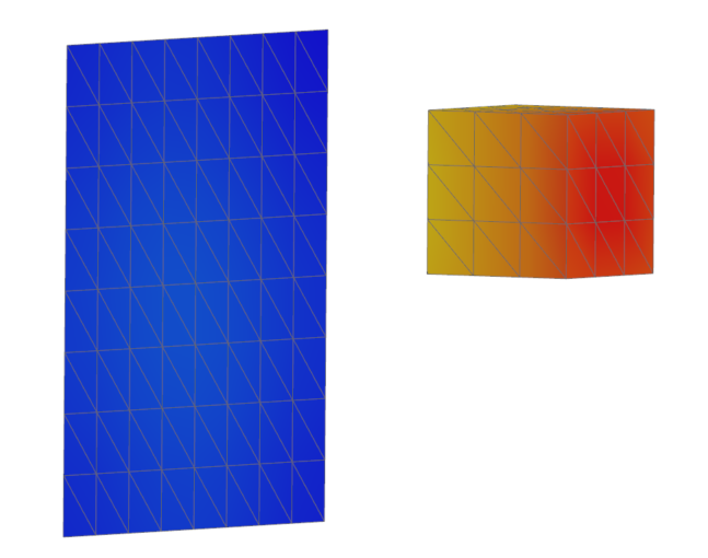
Observe that the temperature distribution is different on each side of the cube. -
Hide cube_mesh to display the temperature of the
middle surface.
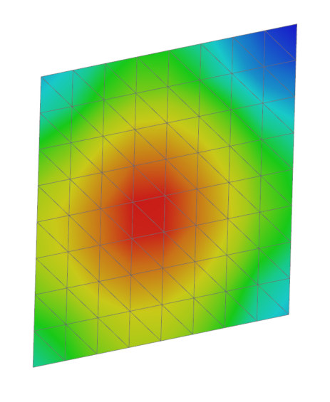
The temperature range is from 70 to 73 °C.
Modify the model to calculate radiation in an enclosure
With the addition of the middle surface:
- Radiation cannot pass from one enclosure to the other.
- No radiation exchange occurs between the two enclosures, therefore they are considered independent enclosures.
- Create multiple independent enclosures if they do not allow radiation exchange.
- Define multiple simple enclosures which lower the computational time required to calculate view factors and shadowing checks.
-
Choose Results tab→Context
group→Return to Home
.
- In the Simulation Navigator, under the Simulation Objects node, right-click Radiation and choose Remove.
- In the Simulation Navigator, show all polygon geometry.
-
Choose Home tab→Loads and
Conditions group→Simulation Object
Type list→Radiation
.
- Make sure that the Enclosure Radiation type is selected.
- In the Name box, type Right Enclosure.
-
In the graphics window, for the Top Side Region, select the following:
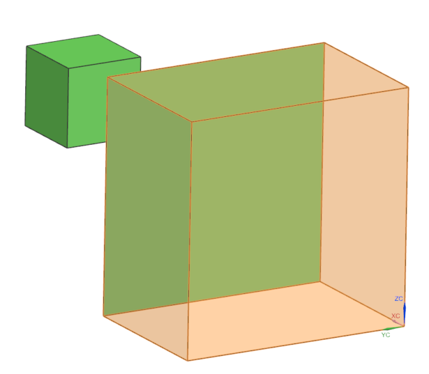
- Five faces from the right enclosure as shown.
- Middle surface face and six cube's faces.Tip: For easier selection, under the Polygon Geometry node, hide Big_enclosure and Small_enclosure.There are 12 faces are selected.
- Five faces from the right enclosure as shown.
- In the Parameters group, clear the Include Radiative Environment check box.
- Click Apply.
- In the Simulation Navigator, show Small_enclosure and hide Simulation Object node.
- In the Name box, type Left Enclosure.
-
Rotate the model and in the graphics window, select five faces of the small
enclosure as top side region.
- Rotate the model 180°.
- In the Simulation Navigator, under the Polygon Geometry node, hide Small_enclosure.
-
In the Bottom Side Region group, click
Select Object and in the graphics window select
the middle face as shown.
In the left enclosure, you select the middle surface in the bottom region because the direction of the shell normals is towards the cube. This ensures that the radiation from the left enclosure does not leak through the wall to the right enclosure. - Click OK.
Solve the model and display results
Solve two independent enclosures separated by the middle surface and containing the cube.
- In the Simulation Navigator, right-click the Solution 1 node and choose Solve.
- Click OK.
- In the Review Results dialog box, click No.
- Close the Information window.
- In the Analysis Job Monitor dialog box, click Cancel.
- In the Simulation Navigator, double-click the Results node.
- In the Post Processing Navigator, under the Thermal node, double-click Temperature-Nodal.
-
Under the Post View 6 →
basic_radiation_fem1.fem → 2D
Elements nodes, hide 2D Elements and
show middle_surface_mesh.
Observe that the temperature distribution is the same as in previous step.