Model radiative exchanges of a satellite
Practice defining an enclosure to model the radiative exchanges of a satellite. The model consists of the High Energy Solar Spectroscopic Imager (HESSI) satellite. It contains four solar panels that have the solar arrays only on one side, a telescope unit in the center, and several instruments. You will learn how to evaluate the radiative exchanges between the satellite and the environment, and inside the satellite where the bus is located, using Radiation simulation objects.
Open the model Simulation file
Open the Simulation file and reset the dialog box settings.
- Choose File→Open and open satellite_radiation\HESSI_Satellite_sim1.sim.
- Choose File→Preferences→User Interface and on the Dialog and Precision page, reset the dialog box memory.
- Click OK.
-
In the Simulation Navigator, explore the following predefined boundary conditions:
- Orbital Heating (Hessi), an orbital heating simulation object to define the HESSI orbit around Earth.
- 21 Thermal Coupling simulation objects to model the conduction between the different parts and components of the satellite.
- Four Merge Set simulation objects to merge selected elements of the mesh into one single element during the solve.
- Two Thermal Loads to model the heat load dissipated by the equipment and the power draw of the solar arrays.
Verify the orientation of the satellite element normals
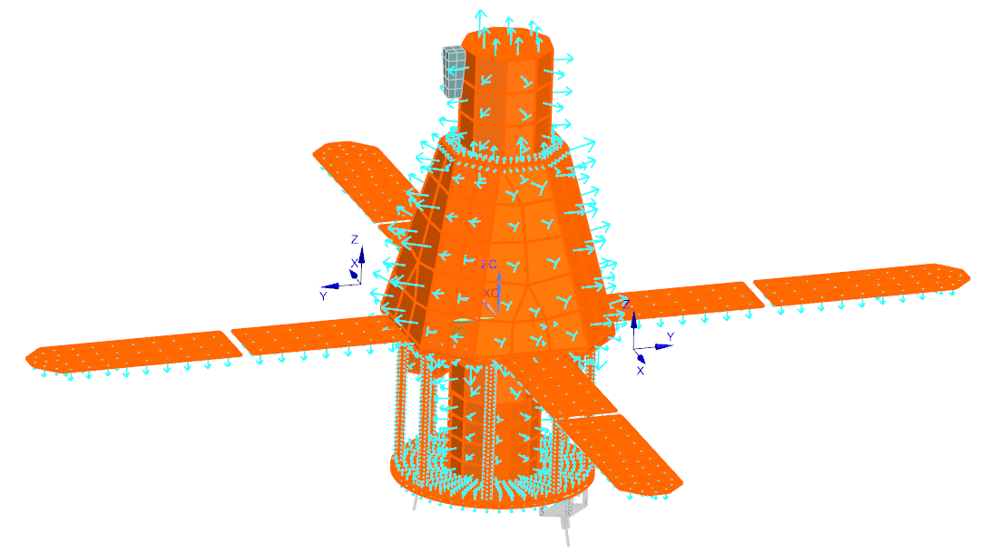
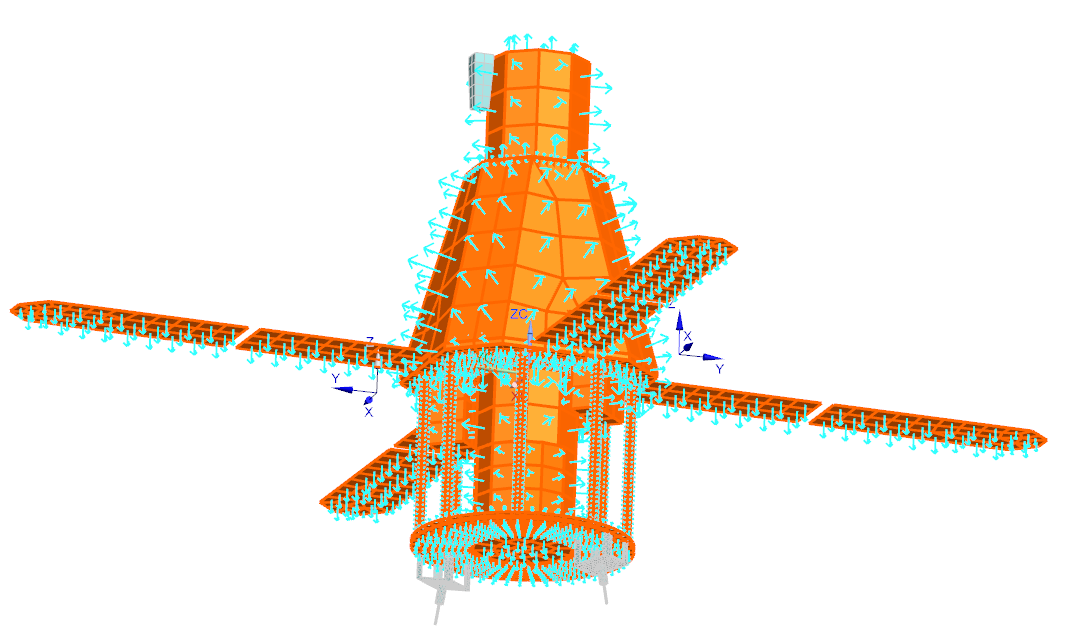
Before defining the enclosure for the Radiation simulation object, you will verify the orientation of the elements to know from which side the surfaces will radiate in the enclosure.
-
Choose Home tab→Checks and
Information group→2D Element Normals
 .
.
- In the graphics window, select all the elements of the satellite meshes.
-
In the Display Settings group, make sure that
Arrows is selected, and click Display
Normals.
Notice that all the element normals are oriented toward the environment. They will radiate from the top side of the surfaces. However, the solar panels have the bottom and top sides in contact with the environment. Thus, they will radiate from both the top and bottom sides of the surfaces.
- Click Close.
Define the satellite radiation to environment
Define a Radiation simulation object to model the radiation to environment of the satellite. You will set the hemicube rendering calculation method.
- In the Simulation Navigator, hide HESSI_thermal_assyfem1.afm to hide the mesh.
-
Choose Home tab→Visibility
group→Invert
 to show the satellite geometry.
-
Choose Home tab→Loads and
Conditions group→Simulation Object
Type list→Radiation
 .
.
- In the Name group, type radiation_to_environment.
-
In the Top Side Region group, select the Group Reference check box, and from the list, select the Top External Radiation group.
This group contains all the satellite surfaces that will radiate to the environment from their top side.
-
In the Bottom Side Region group, select the Group Reference check box, and from the list, select the Solar Panels Bottom group.
This group contains the solar panels surfaces that will radiate from the bottom side.
- In the Parameters group, make sure that the Include Radiative Environment check box is selected to request the solver to calculate the radiation to the environment.
-
From the Calculation Method list, make sure that Hemicube Rendering is selected.
The Hemicube Rendering method is a fast radiation computation method that supports only the diffuse properties and the view factors computation. Since the thermo-optical properties defined in the model do not involve specular properties and that the satellite geometry is not complex, the Hemicube Rendering calculation method represents the ideal choice to compute the satellite view factors.
-
From the Element Subdivision list, select 2.
You can use a higher value for a more detailed analysis but this will increase the computation time.
- Click Apply.
Define the enclosure for the bus of the satellite
Define an enclosure for the satellite bus using the Radiation simulation object. You will set the Hemicube Rendering calculation method.
- In the Simulation Navigator, hide Simulation Object Container and Load Container.
- In the Name group, type bus_enclosure.
-
In the Top Side Region group, select the Group Reference check box, and from the list, select the Top_side_emitting_region group.
This predefined group contains all the surfaces of the bus enclosure that will radiate from the top side.
-
In the Bottom Side Region group, select the Group Reference check box, and from the list, select the Bottom_side_emitting_region group.
This predefined group contains all the surfaces of the thermal blanket that will radiate from the bottom side.
- In the Parameters group, clear the Include Radiative Environment check box to disable the radiation to the environment calculation of the elements part of the enclosure.
- Click OK.
Edit the solver parameters
- In the Simulation Navigator, right-click the Solution 1 node and choose Edit Solver Parameters.
- On the Radiation Parameters tab, select the Use Radiation Patches check box.
- This functionality reduces the computation time by temporarily merging adjacent elements for the purposes of calculating radiative exchange.
-
Make sure that the Ignore Specular and Transparent Effects for Radiation Request Calculations check box is selected.
This option forces the solver to use the hemicube rendering calculation method even if specular or transmissive thermo-optical properties are used in the model. When you clear this option, the thermal solver automatically enables the deterministic calculation method for radiation enclosures containing elements with specular or transmissive thermo-optical properties.
- Click OK.
Solve the model
- In the Simulation Navigator, right-click the Solution 1 node and choose Solve.
-
Click OK.
If you have a labeling error, do the steps 3 to 5. If there is no error, do step 6.
-
In the Simulation Navigator, right-click the HESSI_Satellite_sim1.sim node and select Simulation Label Manager to resolve the label conflicts.
In the Labels group, on the Modeling Objects tab, observe that the Status is set to Conflict.
- In the Automatic Label Resolution group, click Automatically Resolve.
- Click OK.
- Wait for the solve to end, before proceeding. The solve takes around 10 minutes to complete.
- In the Review Results dialog box, click No.
- Close the Information window.
- Click Cancel on the Analysis Job Monitor dialog box.
Review the results
- In the Simulation Navigator, double-click the Results node.
- In the Post Processing Navigator, expand the Thermal → Increment 17, 5.792E+03s nodes, and double-click the Absorbed Radiative Flux, PLANET IR - Elemental node.
-
Choose Results tab→Post View
group→Edit Post View
 .
.
- On the Result tab, from the Units list, select W/m2.
- On the Display tab, in the Edges & Faces group, from the Edges list, select Feature.
-
Click OK.

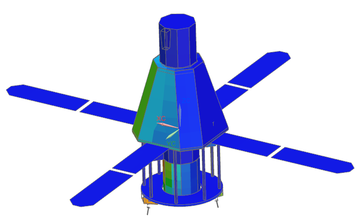
Notice that only one side of the satellite absorbed radiation from Earth. You can rotate the model to visualize all the sides of the satellite. -
In the Post Processing Navigator, expand
Post View 1 → Mesh
Collectors →
HESSI_thermal_assyfem_fem1.afm, and hide
thermal_blanket_fem1.fem to hide the thermal
blanket and display the results within the bus enclosure.
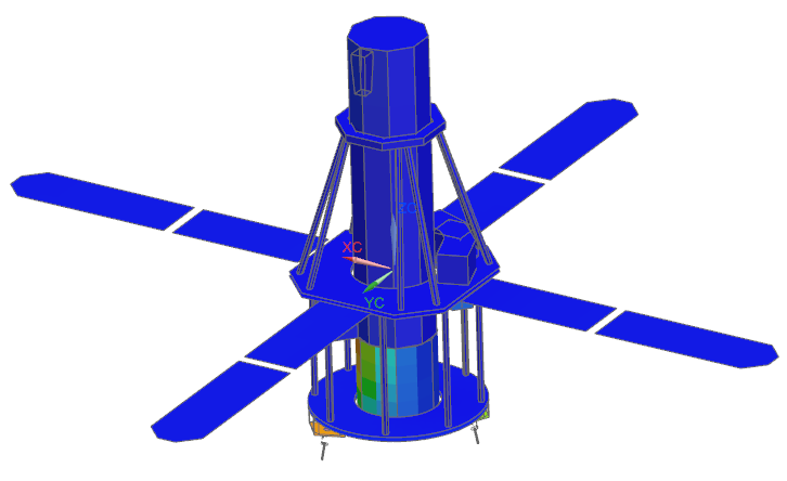
Notice that no radiation from Earth was absorbed by the satellite components located within the bus enclosure due to the thermal blanket.