Meshing nuts and bolts
This topic explains how to accurately represent bolts and nuts in two-dimensional axysymmetric models and how to mesh these components for thermal analysis.
This lesson may include hands-on exercises. Review the Discussion section for background information or click the button to proceed to the practical section.
Discussion
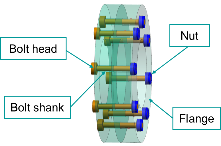
The following example shows a 3D model of two flanges fastened together using eight bolts and nuts.
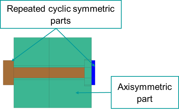
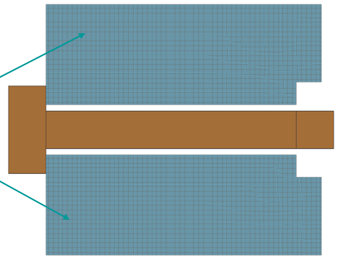
The 2D axisymmetric representation of this 3D model consists of:
- An axisymmetric region meshed with axisymmetric elements (shown in green in the following image), because the geometry is revolved around the axis of rotation.
- Repeated cyclic symmetric features, such as nuts and bolts, meshed with plane stress elements (shown in brown in the following image). Plane stress elements require associated thickness and number of instances definitions.
Recommendations for creating 2D axisymmetric representation
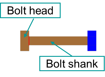
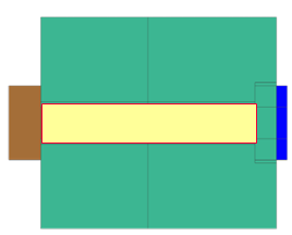
For accurate thermal contact modeling, divide the following faces to correctly represent bolt and nut geometry and contact regions:
- Separate the bolt head and shank because these regions have different thickness.
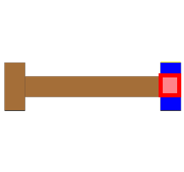
- Create an intersection face between the overlapping nut and bolt regions to represent the bolt–nut contact area.
- Create an intersection face between the bolt and flange to represent the thermal contact interface.
| Bolt regions with different thickness. | Bolt-nut contact interface (red surface) | Bolt-flange contact interface (yellow surface) |
|---|---|---|
|
|
|
You must divide the geometry before applying associative thicknesses to the bodies. In addition to proper thickness definition, thermal contact accuracy also depends on the mesh size and coupling resolution. For more information, see How do I create thermal connections for axisymmetric models with bolts and nuts?
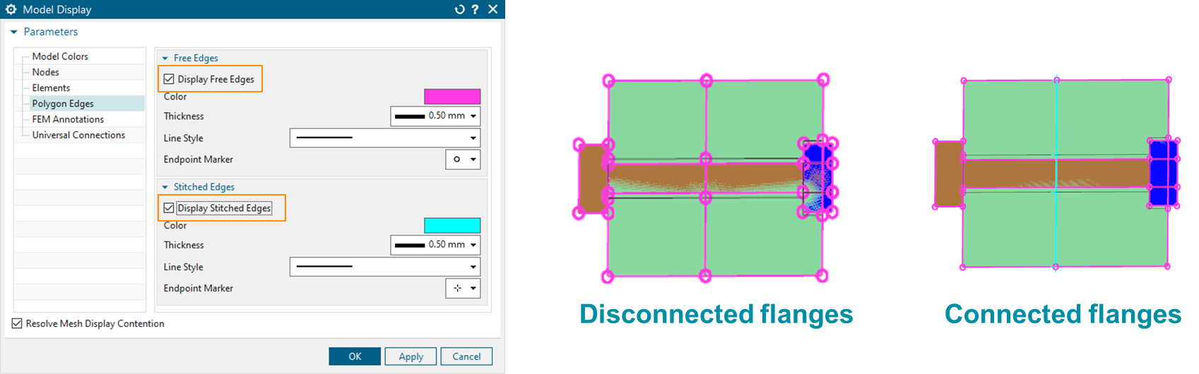
After dividing the faces, inspect and stitch free edges to connect geometrically disconnected solid bodies to model thermal conduction correctly. In the following example, two flanges are connected using stitched free edges.
Meshing 2D bolts
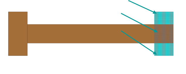
- Mesh the three bolt faces separately using plane stress elements.
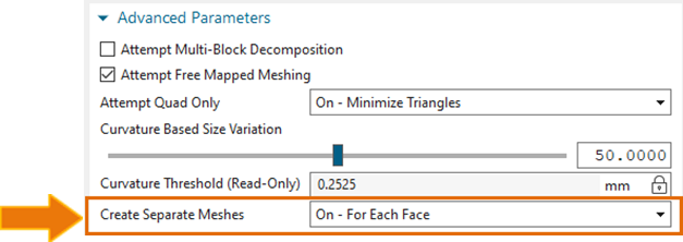
- In the 2D Mesh dialog box, from the Create
Separate Meshes list, select For Each
Face to create separate meshes for each associative
thickness region.
- Define the mesh thickness, number of instances, and centerline separately
using Edit Mesh Associated Data.
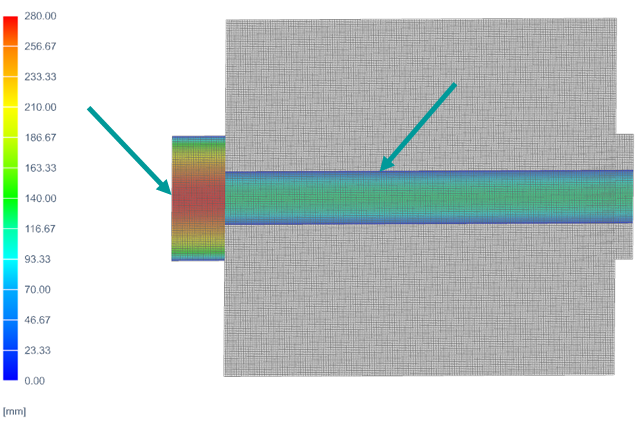
For bolts, set the Thickness Source to Bolt. The software automatically calculates the equivalent thickness of a bolt pattern meshed with plane stress elements.

- The total masses of the 3D and 2D bolt representations are equal using Solid Properties.
- The thickness on the edges is equal to zero.
- The thickness at the centerline is equal to the bolt diameter multiplied by the number of instances.
Use the right-click Plot Contour command to display the thickness as shown in the following image.
Based on the 3D bolt model, the volume of each bolt mesh is:
- is the radius of each bolt element.
- is the length of each bolt element.
- is the number of bolt instances.
Meshing 2D holes
- Mesh each hole separately using plane stress elements.
- In the Edit Mesh Associated Data dialog box, specify the number of holes and set Thickness Source to Hole.
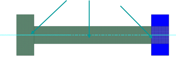
- Define the centerline location for the hole. Use the inferred centerline
definition option only when the hole geometry consists of four edges.
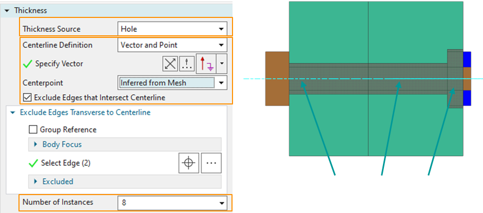
- The blue centerline is displayed in the correct location.
- The thickness on the top edge equals .
- The thickness on the bottom edge equals .
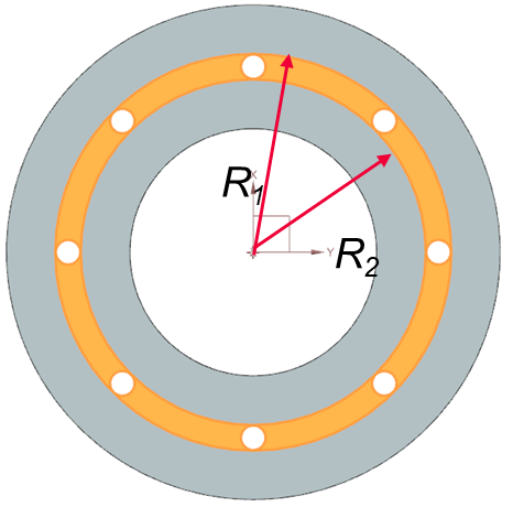
Based on the 3D model, the volume of each hole mesh is:
- is the volume of the hole material displayed in yellow.
- is the top radius of the solid region around the holes.
- is the bottom radius of the solid region around the holes.
- is the radius of the hole element.
- is the length of the hole element.
- is the number of hole instances.
Meshing 2D nuts
- Create separate meshes for the three nut faces using plane stress
elements.
Because the model contains overlapping 2D faces, make sure to select the nut faces rather than the bolt face.
- In Mesh Associated Data, specify:
- The number of nut instances.
- The thickness using Field/Expression.
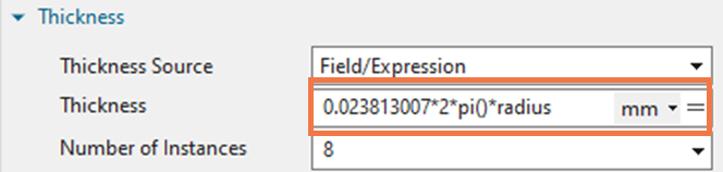
To define the thickness for each nut mesh, use an expression based on the area factor associated with each nut region. This approach ensures that the total mass remains consistent between the 3D and 2D representations.
- Define the 2D nut thickness as:
- Calculate the total mass of the 2D nut using Solid Properties.
- Determine the total mass of the 3D nut.
- Compute a correction factor by dividing the 3D nut mass by the 2D nut mass.
Meshing 2D flanges
Mesh the flanges using axisymmetric elements.
After meshing all components, inspect the total volume and mass and compare them with the original 3D model or hand calculations. To inspect mass, volume, and surface area, right-click the mesh and use the Solid Properties command.
The next step in the modeling of bolts and nuts is creating thermal connections between these components which is described in Connecting bolts and nuts in the axisymmetric models.
Hands-on material
To gain experience with the topics discussed here, complete the following: