Abstract 3D geometry to 2D plane and apply 2D thickness
Learn how to abstract a cyclically symmetric 3D gas turbine strut assembly into a 2D model and apply thickness definitions for thermal and structural simulation efficiency.
Introduction
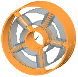
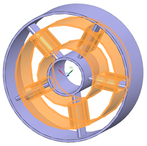
3D gas turbine components often exhibit cyclic symmetry or axisymmetric behavior. In such cases, modeling the thermal and structural response in 2D can significantly reduce simulation time while maintaining accuracy.
The workflow includes:- Creating an idealized part.
- WAVE-linking the geometry.
- Generating curves with the Revolve Outline command.
- Creating surfaces using the Bounded Plane tool.
- Dividing sheet bodies into multiple faces.
- Review how to display and evaluate free edges.
- Assign 2D thickness values derived from the original 3D geometry.
- Verify the 2D element volume against the 3D model to ensure accuracy.
Open the part file
Open the part file and reset the dialog box settings.
- Choose File→Open and open abstraction\strut.prt.
- Choose File→Preferences→User Interface and on the Dialog and Precision page, reset the dialog box memory.
- Click OK.
Create the idealized part
Use an idealized part to simplify and modify geometry for simulation while keeping the original CAD model unchanged.
-
On the Application tab, click
Pre/Post
 .
.
- In the Simulation Navigator, right-click the strut.prt file and choose New Idealized Part.
- Click OK twice.
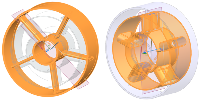
Create an associative copy of the geometry
-
On the Application tab, click
Modeling
 .
Newly created idealized parts open in the Pre/Post environment by default. Switching to the Modeling environment allows you to access the complete set of modeling tools.
.
Newly created idealized parts open in the Pre/Post environment by default. Switching to the Modeling environment allows you to access the complete set of modeling tools. -
Choose
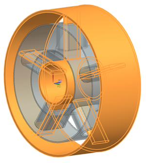
 to create an associative copy of the geometry
you want to modify to isolate the analysis geometry while keeping a link to
CAD updates.
to create an associative copy of the geometry
you want to modify to isolate the analysis geometry while keeping a link to
CAD updates.
-
Select the Body type from the list, in the graphics
window select one of the two bodies, and click
OK.
-
Repeat the wave linking process for the second body.
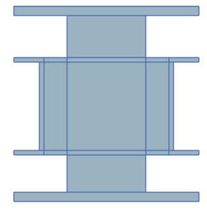
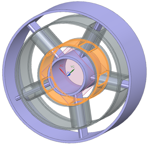
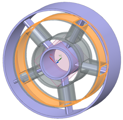
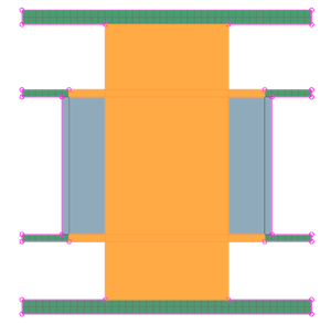
After WAVE linking, the model contains four bodies.
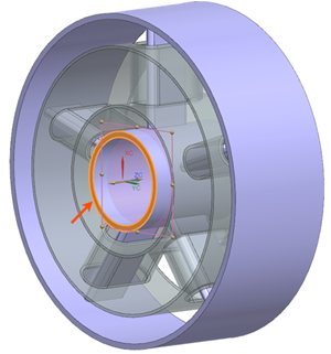
Create the 2D sheet bodies
Use the Revolve Outline command to create a 2D representation of a cyclically symmetric 3D gas turbine strut.
-
Choose
 to project 3D geometry onto the
axisymmetric plane.
to project 3D geometry onto the
axisymmetric plane.
-
Select each body individually to generate curves.
-
Choose
 to create a bounded plane using the outer
curves.
to create a bounded plane using the outer
curves.
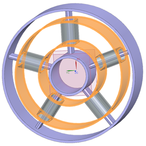
-
Select the outer 12 curves as shown.
-
Repeat the steps 3 to 5 to create bounded plane for the second body.
12 curves are selected.
-
Choose
 to subdivide sheet bodies into multiple
faces.
to subdivide sheet bodies into multiple
faces.
-
For the first body, select the shown one face.
-
Select the shown 14 objects.
You can verify that three faces are created.
-
For the second sheet body select the following one face.
-
Select the shown 16 objects.
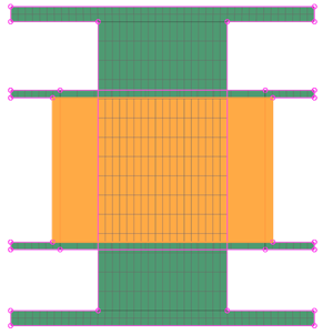
You can verify that nine faces are created.
Tip:On the Top toolbar, from the Type Filter list, select Face, then select the model to identify and explore the newly created faces.12 faces are created.
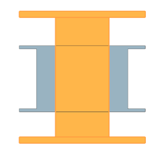
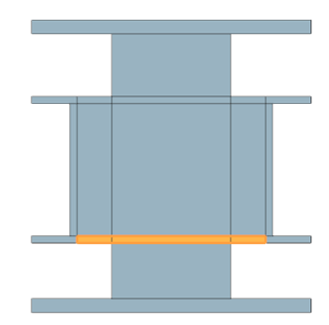
Split the body
- Each 3D region corresponds directly to a specific 2D face.
- Features like holes, inner/outer cylinders, or thickness changes are isolated.
- Volume measurements become physically meaningful for each 2D region.
-
Choose
 to divide the wave-linked bodies
using edge extrusions.
to divide the wave-linked bodies
using edge extrusions.
-
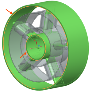
Select the shown body as a target body.
-
From the Tool Option list, select
Extrude, and select the shown curves.
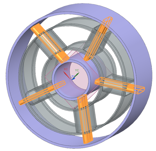
-
Repeat the steps 2 to 4 for the second linked body. Select the shown
curves.
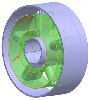
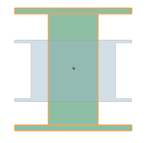
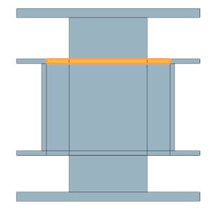
These curves are selected because they define the radial limits of the regions that must be isolated to obtain accurate, region-specific 3D volume measurements for 2D thickness definition.
-
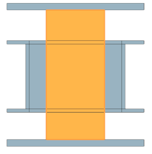
To accurately measure volumes in regions containing holes, the second body
must be split twice in the XY plane. Choose
 to create datum planes in the XY plane to
perform this additional subdivision.
to create datum planes in the XY plane to
perform this additional subdivision.
-
From the list, select At Distance and select the
shown surface.
-
Split the shown inner and outer cylinders using the created datum
planes.
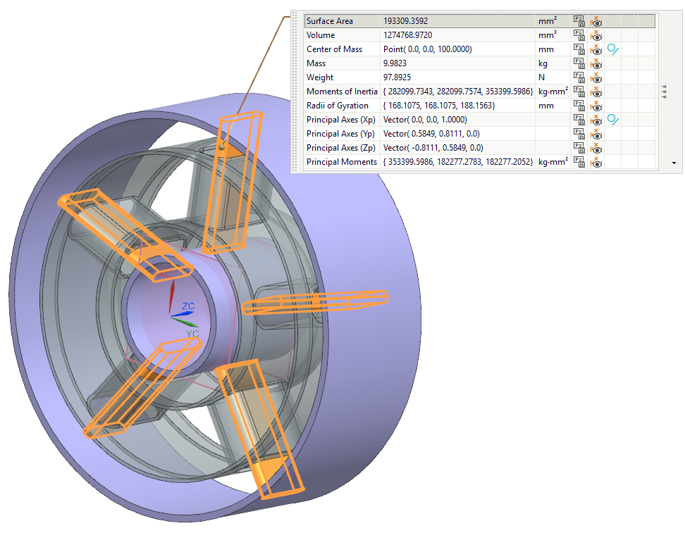
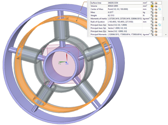
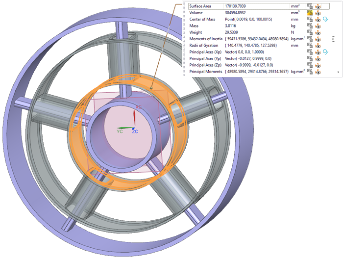
Measure volumes and create measurements
-
On the Top border bar, from the Type Filter list,
select Solid Body, and select the shown bodies.
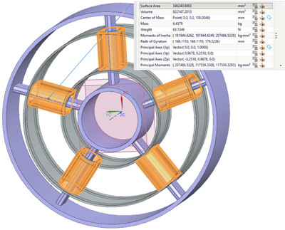
-
Click the P
 button to save each volume
measurement as an expression that will be referenced later in FEM.
Notice that the Measure Body is created in the Part Navigator.
button to save each volume
measurement as an expression that will be referenced later in FEM.
Notice that the Measure Body is created in the Part Navigator. -
Repeat the same process for all bodies shown below.
-
In the Part Navigator, click on the
Measure Body and rename the created expression as
follows:
Body 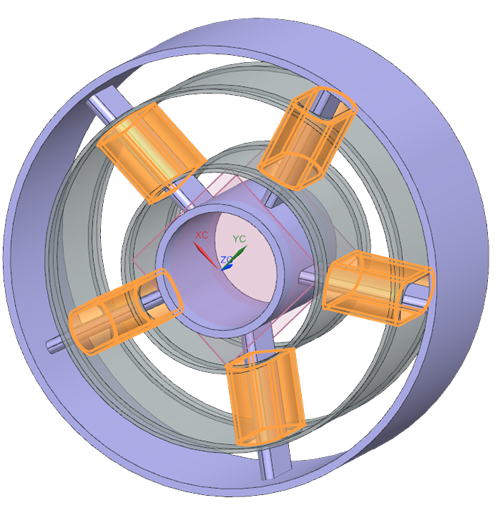
Expression name V_strut_shield V_strut V_inner V_outer -
Rename created expressions as follows:
Face 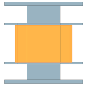
Expression name A_strut_shield A_strut A_inner A_outer
Create the FEM and apply thicknesses
Create a 2D FEM, apply axisymmetric and plane stress meshes with thickness expressions, and verify that the 2D model matches the 3D volume within acceptable tolerance.
-
Choose
.
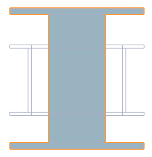
-
From the list, select Polygon Edges and select the
Display Free Edges check box.
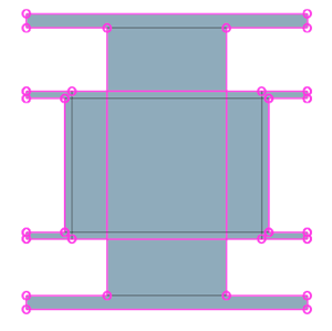
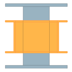
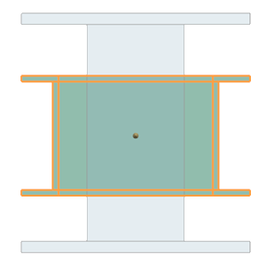
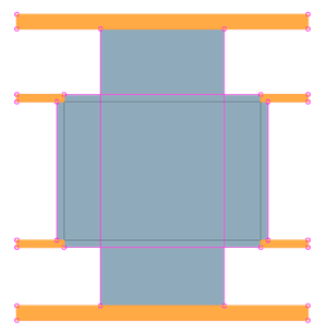
The two sheet bodies are now displayed with their free edges. Identifying free edges is important because edges in contact do not conduct heat by default. This view helps determine where thermal couplings must be defined or where edge stitching is required to ensure proper heat transfer.
-
Choose
 to apply a 2D axisymmetric mesh
to the appropriate regions.
to apply a 2D axisymmetric mesh
to the appropriate regions.
-
Select the shown regions.
-
Next to Element Size, click Automatic
Element Size
 to let the software to compute
it.
to let the software to compute
it.
-
Select the shown regions.
-
For the remaining faces, create a 2D mesh using Plane Stress
Linear Quadrilateral elements with the automatic element
size but without creating separate meshes. These faces are grouped together
because they share the same thickness definition.
-
In the Source Expressions, select all thickness
expressions, and click Add to Destination
 .
.
Verify a volume check on the meshes
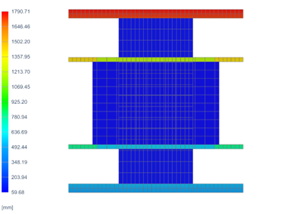
Verify that the 2D model matches the 3D volume within acceptable tolerance. From the volume measurements in 3D, the total volume is 8539473 mm3.
-
In the Simulation Navigator, right-click the
2D Collector and select Plot Thickness
Contours to visually verify thickness definitions.
Subdivide geometry further if thickness varies significantly in radial or axial directions. Use constant or manually defined thickness values if associativity with 3D geometry is not required.