Map the heat distribution of a solar panel
Practice to create a mapping solution on the target structural model, mapping the temperature results for a specific time step, from a source thermal model, and run a structural analysis.
Open the thermal Simulation file
Open the Simulation file and reset the dialog box settings.
- Choose File→Open and open panel/panel_s_thermal.sim.
- Choose File→Preferences→User Interface and on the Dialog and Precision page, reset the dialog box memory.
- In the Simulation Navigator, expand and explore all nodes.
-
Choose File→Open and open panel/panel_s_structural.sim.
Notice that tetrahedral type elements are used.
Display the thermal results
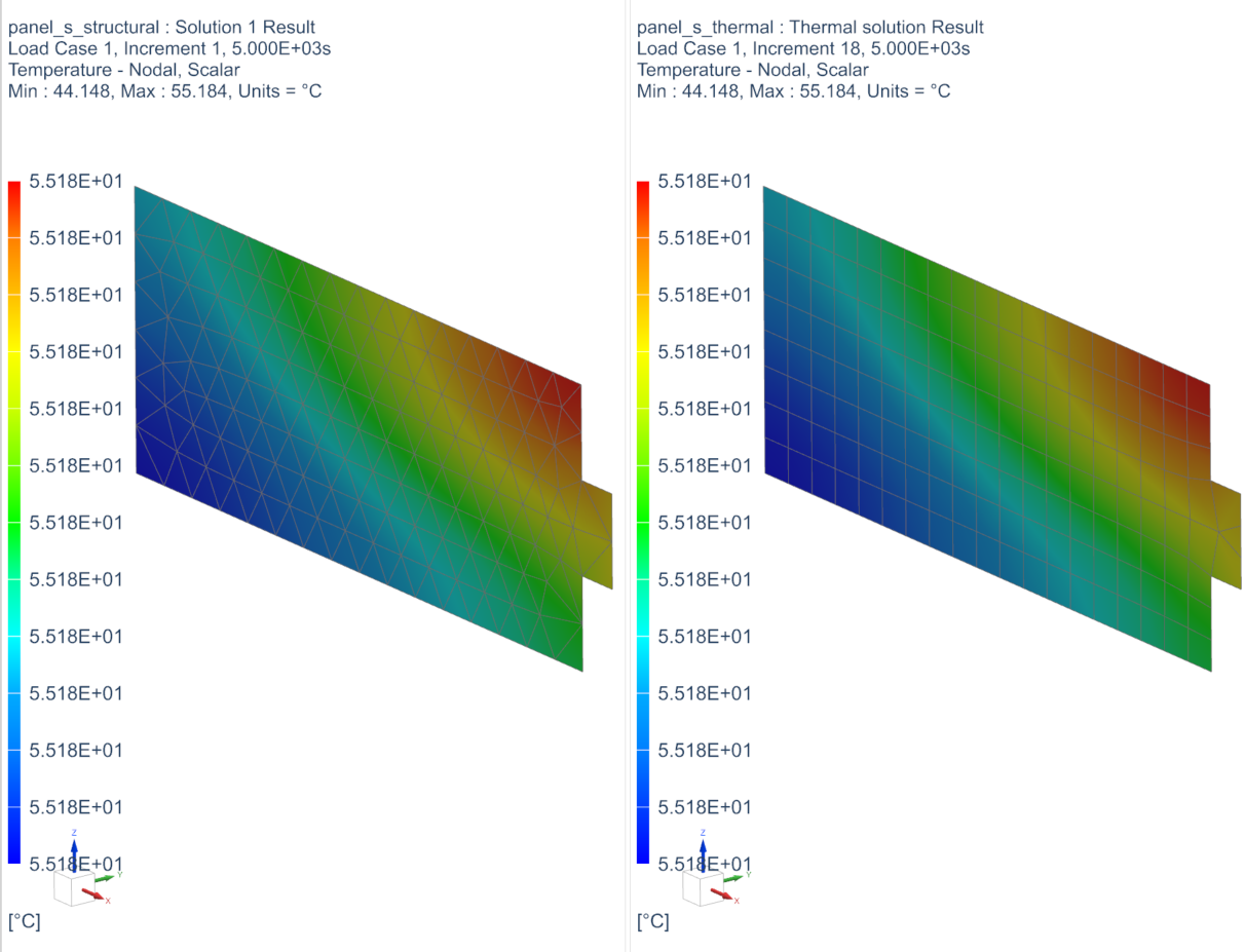
Display the temperatures at 5000 seconds, which you will be mapped onto the structural model later.
- Click the (Simulation) panel_s_thermal.sim tabbed window.
- In the Simulation Navigator, under the Thermal solution node, double-click the Results node.
- In the Post Processing Navigator, expand the Thermal→Increment 18, 5000 sec nodes and double-click the Temperature - Nodal node.
-
Expand the Post View 1→panel_f_thermal.fem→2D Elements nodes and hide Black Side Panel Collector.
Create the mapping solution
Create a mapping solution on the structural Simulation file, which you will open first. The mapping solution will point to the thermal solution results.
- Click the (Simulation) panel_s_structural.sim tabbed window.
- In the Simulation Navigator, right-click the panel_s_structural.sim node and choose New Solution.
-
In the Solution group, from the
Solver list, select one of the following options:
Simcenter 3D Thermal/Flow, Simcenter
3D Electronic Systems Cooling, Simcenter 3D Space
Systems Thermal, or Simcenter 3D
Multiphysics.
Note that for this activity the Simcenter 3D Space Systems Thermal solver is selected.
- From the Analysis Type list, select Mapping.
- Click Create Solution.
- On the Mapping Details tab, in the Data Source and Destination group, click Browse and select the panel_s_thermal-Thermal_solution.bun file.
- In the Transient Times group, in the Select Output Times box, type 5000.
- On the Optional Output tab, in the Output Format group, select the Create Nastran Solution check box.
- Click OK.
Solve the mapping solution
Solve the mapping solution you just created on the structural model.
- In the Simulation Navigator, right-click the Solution 1 node and choose Solve.
- In the Solve dialog box, click OK.
- Wait for the mapping solve to end, before proceeding.
- In the Analysis Job Monitor dialog box click Cancel.
- Close the Information window.
Display mapped thermal results
Display the mapped thermal results on the structural panel simulation file at time 5000 sec.
- In the Simulation Navigator, under the Solution 1 node, double-click the Results node.
- In the Post Processing Navigator, expand the Thermal→Increment 1, 5.000E+03s nodes and double-click the Temperature – Nodal node.
-
Expand the Post View 2→panel_f_structural.fem→2D Elements and hide Black Side Panel Collector.
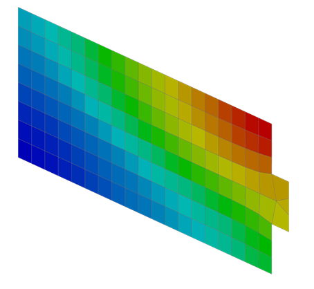
You mapped temperatures at a specific time: 5000 seconds. The temperature is approximately 55 °C and uniform.
-
Right-click the (Simulation) panel_s_structural.sim tabbed window and choose Layout→2 Tabbed Groups
 .
.
-
Choose Results tab→View Layout group→Synchronize Views
 .
.
- Select both graphics windows.
-
In the View Settings dialog box, click
OK.
-
Choose Results tab→Context group→Return to Home
 .
.
Constrain the panel
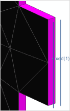
Apply a fixed constraint at one of the sides of the satellite panel.
- Click the (Simulation) panel_s_structural.sim tabbed window.
- In the Simulation Navigator, double-click the Mapping Nastran node.
- Expand the Subcase1→Loads→Temperature Set – Temperature1 nodes.
- Notice the Temperature1 load, which was created by the mapping process.
-
Choose Home tab→Loads and Conditions group→Constraint Type list→Fixed Constraint
 .
.
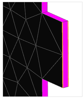
- On the Top Border bar, from the Type Filter list, select Polygon Edge.
-
Select the following two polygon edges on the model.
-
Click OK.
Solve the structural solution
Solve the structural model with the temperature preload.
- In the Simulation Navigator, right-click the Mapping Nastran node and choose Solve.
- Click OK.
- Wait for the solve to end, before proceeding.
- In the Review Results dialog box, click No.
- In the Analysis Job Monitor dialog box, click Cancel.
- Close the Information window.
Display the structural results
Animate displacement results to compare the deformation between top and bottom sides.
- In the Simulation Navigator, expand the Mapping Nastran node and Results nodes.
- Right-click the Structural node and select Specify.
- In the Results File Name group, click Browse and select panel_s_structural-mapping_nastran.op2.
- Click OK twice.
-
In the Post Processing Navigator, double-click the Structural node→Displacement Nodal node.
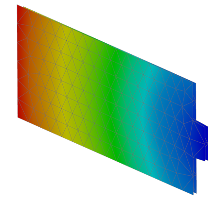
The average displacement is approximately 0.110 mm. - Choose Results tab→Animation group→Play.