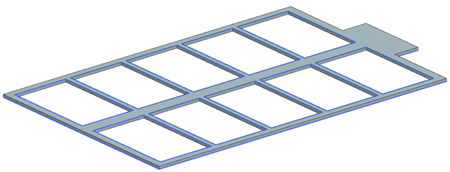
Create a simple model using a sketch profile
Create a new part and a simple structure for solar panels on a spacecraft by extruding the sketch.
Create a part file
Create a part file.
-
Choose File tab→New
 .
.
- Create a new part file using the Model template and name the file solar_panel.prt.
- Click OK.
Define a sketch profile
Define a sketch profile.
-
Choose Home tab→Construction
group→Sketch
 .
.
- In the graphics window, select the Top plane.
- Click OK.
-
Choose Home tab→Curve
group→Line
 .
.
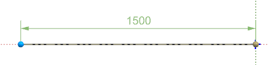
- Click the center of the graphics window and move the mouse to the left until the line has reached a length of 1500.
-
Click the graphics window to fix the line.
- In the Line dialog box, in the Size group, in the Length box, specify 2250 mm and press Enter.
-
In the Angle box, specify 90
degrees and press Enter.
To view the whole profile, right-click in the graphics window and choose Fit. - Click Close.
-
Using either method, define the remaining profile lines as shown in the
following image.
- To use your mouse, make sure to uncheck the lock for both the Size and Angle boxes to freely click and drag a new line.
- To use the Line dialog box, specify the Size and Angle values of the next line, and click the end of the last line.
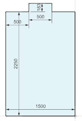
- Close the Line dialog box.
-
Choose Home tab→Sketch
group→Finish
 .
.
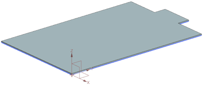
Extrude the sketch
Extrude the sketch to create the base of the solar panel model.
-
Choose Home tab→Base
group→Extrude
 .
Notice that the sketch is already selected.
.
Notice that the sketch is already selected. - In the Limits group, in the end Distance box, type 20 mm.
-
Click OK.
Create a sketch on existing sketch plane
Create a sketch on existing sketch plane.
-
Choose Home tab→Construction group→Sketch
.
-
Select the face of the extruded solar panel.
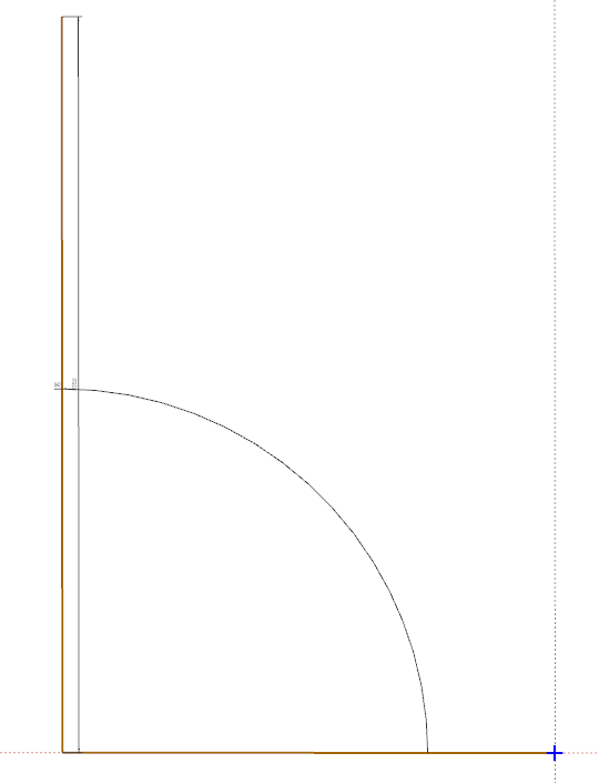
Move your mouse toward the corner to have the coordinate system set as shown on the image.
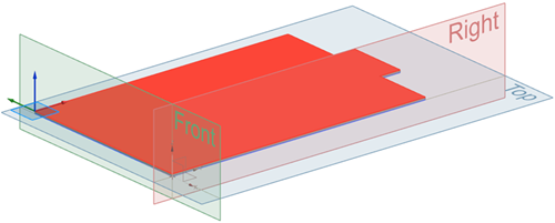
- Click OK.
-
Choose Home tab→Curve group→Rectangle by Three Points
 .
.
- In the Location group, click Point Dialog.
- From the list, select Cursor Location.
- In the Output Coordinates group, in the XC box, type -1450 and press Enter, in the YC box, type 50 and press Enter, and in the ZC box, type 20 and press Enter.
- In the Size group, in the Width box, type 400, and press Enter.
- In the Angle box, type 0, and press Enter.
- In the Height box, type 650, and press Enter.
-
Click within the rectangle's outline. Make sure that the shape is set as shown on the image.
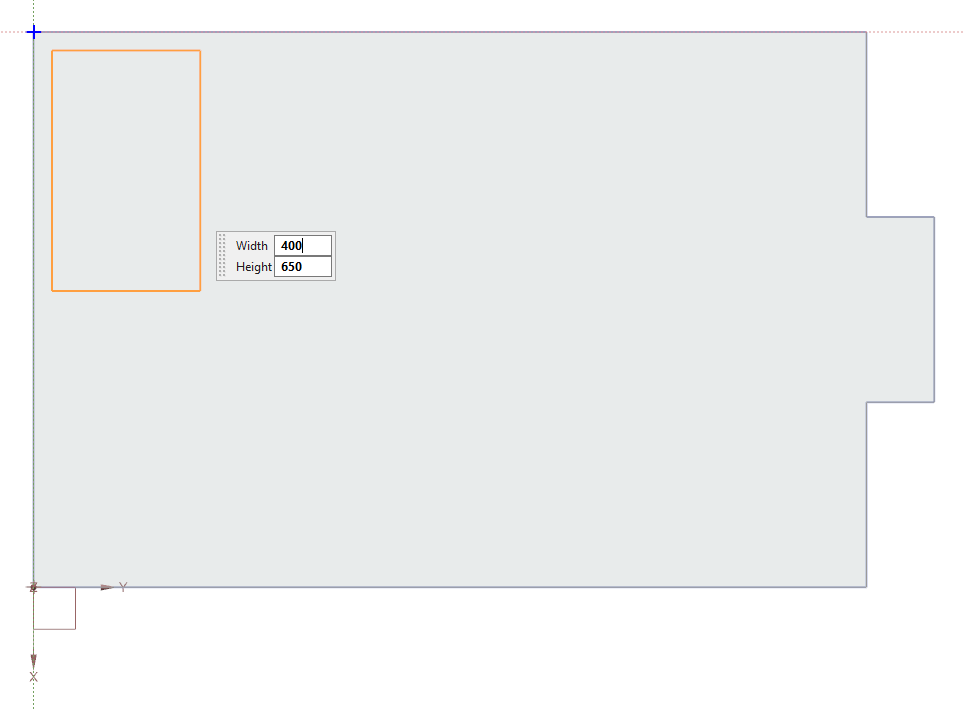
- Close the dialog box.
-
Choose Home tab→Sketch group→Finish
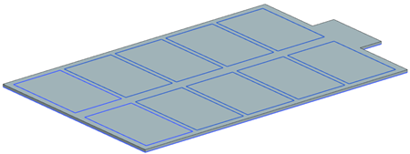
Create a pattern of rectangular features on the solar panel base
Create a pattern of rectangular features on the solar panel base.
-
Choose Home tab→Base
group→Pattern Feature
 .
Notice that the sketch is already selected.
.
Notice that the sketch is already selected. - In the Direction 1 group, click Specify Vector and in the graphics window, select the Y-axis direction.
- In the Count box, type 5.
- In the Pitch Distance box, type 435 mm.
- In the Direction 2 group, select the Use Direction 2 check box.
- Click Specify Vector and in the graphics window, select the X-axis direction.
- In the Count box, type 2.
- In the Pitch Distance box, type 750 mm.
-
Click OK.
Extrude using Boolean operations
Extrude using Boolean operations.
-
Choose Home tab→Base
group→Extrude
- In the graphics window, from the Curve Rule list, select Connected Curves.
-
Select the curve of each rectangle.
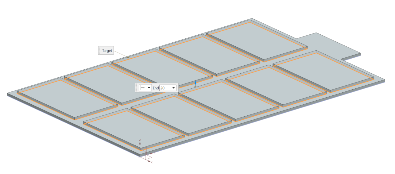
40 curves are selected. - In the Limits group, in the end Distance box, type -20 mm.
- In the Boolean group, from the Boolean (Unite) list, select Subtract.
-
Click OK.