Creating midsurfaces before meshing
Practice the workflow for creating midsurfaces using various midsurfacing strategies, and then generate a 2D mesh.
Open the FEM file
Open the FEM file and reset the dialog box settings.
- Choose File→Open and open midsurface/P009_midsurf_cap_fem1.fem.
- Choose File→Preferences→User Interface and on the Dialog and Precision page, reset the dialog box memory.
- Click OK.
Display the idealized part
Generate a 2D mesh on the part. Before you do this, you must generate a midsurface on the solid part.
-
In the Simulation Navigator, right-click the idealized part and choose Load.
Both the idealized part and the master part are loaded.
- Right-click the idealized part and choose Open in Window.
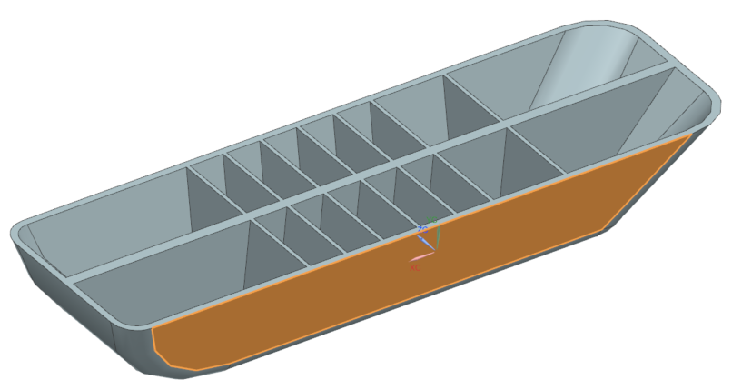
Midsurface the outer walls
Midsurfaces are defined in the idealized part. You will use thickness to select face pairs to define the midsurface. In this part, the outer walls are about 2.5 mm thick, the lateral ribs are about 1.5 mm thick, and the central rib is about 4 mm thick.
-
Choose Home tab→Geometry
Preparation group→Midsurface by Face
Pairs
 .
.
- In the Manual Face Pairing group, click Select Side 1 Faces.
- In the Scene Bar Options toolbar, from the Face Rule list, select Tangent Faces.
-
In the graphics window, select one of the outer faces.
14 tangent outer faces are selected. -
In the Manual Face Pairing group, in the Side 2 Search subgroup, in the Search Distance box, type 3 mm.
By specifying a search distance of 3 mm, the software will pair faces separated by 3 mm or less with the faces on the outside of the part.
-
Click Find Side 2 Face Candidates.
60 faces are selected for the side 2. The midsurface is now complete for the outer walls of the part. Next, you will create midsurfaces on the internal ribs of the part.
Leave the Midsurface by Face Pairs dialog box open for the next step.
Midsurface the thin ribs
Set the face pairing strategy to Thickness to have the software automatically pair faces according to their thickness.
- In the Automatic Face Pairing Options group, from the Strategy list, select Thickness.
- In the graphics window, select the part.
-
In the Thickness box, enter 3
mm and press Enter.
By specifying a search distance of 3 mm, the software pairs faces separated by 3 mm or less. However, faces that are already paired are excluded from the search.The thin ribs are now midsurfaced.
Leave the Midsurface by Face Pairs dialog box open for the next step.
Midsurface the center rib
Increase the thickness value to create a face pair for the center rib.
Leave the Midsurface by Face Pairs dialog box open for the next step.
Midsurface the part automatically
Create midsurfaces automatically for this part. The manual method is required for parts that are too complex for this software to midsurface automatically. However, the current part is not too complex. To do so, you must first delete the current face pairs. Begin by selecting all face pairs that you have created.
-
In the Manual Face Pairing group, select Show Automatic Pairs.
This expands the list of created face pairs.
- From the list, Shift-select all 9 face pairs.
- Click Remove.
-
In the banner of the dialog box, click Reset.
In the Solid Bodies group, Select Body is highlighted.
-
In the graphics window, select the body.
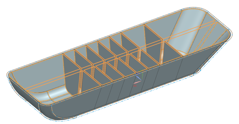
118 faces are automatically selected and midsurfaces are created.
-
In the Simulation Settings group, notice that Stitch Edges is enabled.
The software automatically stitches the free edges. This eliminates gaps between surfaces and overlapping internal free edges.
- Click OK.
Mesh the model
Mesh the model.
- In the graphics window, click the FEM tab.
-
In the Simulation Navigator, hide Polygon
Body (1).
The midsurfaces will still be visible.
-
Choose Home tab→Mesh
group→2D Mesh
 .
.
- Drag a box around the midsurface bodies to select them.
- In the Element Properties group, keep the default element type.
- In the Mesh Parameters group, next to Element Size, click Automatic Element Size.
- Click OK.