
VVT31 - Adiabatic wall temperature on the edge of an axisymmetric plate
| Solution | Test case |
|---|---|
| Case A | SVTEST264 |
| Case B | SVTEST265 |
Description
The purpose of this validation test is to determine the adiabatic wall temperature of an axisymmetric plate for two cases and to compare the results with the analytical solution:
- Case A: The solver automatically predicts the adiabatic wall temperatures.
- Case B: The solver uses the specified recovery factor to compute adiabatic wall temperature.
Geometry
The axisymmetric modeling technique is used to model an axisymmetric plate with a length of 270 mm and a width of 50 mm. A line between the axisymmetric plate and the axis of rotation is used to model a duct with a mass flow. The axisymmetric edge of the plate and the duct are located from the axis of rotation on distances of 679 mm and 650 mm, respectively.
Simulation model
A 2D mesh is generated using axisymmetric linear quadrilateral elements that are 6.25 mm in size. The 1D elements are axisymmetric ducts with a mass flow.
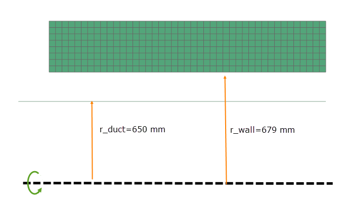
The meshed elements have the following material and physical properties:
- Shell material for the plate: AISI_310_SS
- Mass density: ρ = 7928 kg/m3
- Environmental fluid material: Air
- Mass density: ρ = 1.2041 kg/m3
- Specific heat at constant pressure Cp = 1007 J/kg·K
The following boundary conditions are applied:
-
Convection Coupling type of the Thermal Coupling - Convection simulation object between the edge of the plate and the duct with the heat transfer coefficient equal to 1e6 Btu/(hr·ft2·ºF). The rotational effects option is set to Correct for Wall Rotation with the swirl ratio equal to 0.1. The Adiabatic Wall Temperature for Heat Transfer Calculations check box is selected.
In Case A: Adiabatic Wall Temperature is set to Automatic and the Specify Recovery Factor check box is cleared.
In Case B: Adiabatic Wall Temperature is set to Automatic, the Specify Recovery Factor check box is selected, and Recovery Factor is equal to 0.875.
- Duct Fan/Pump type of Duct Flow Boundary Conditions applied to the duct with a mass flow of 1 lbm/s.
- Duct Total Pressure type of Duct Flow Boundary Conditions applied to the duct inlet with a total pressure of 384.53 psi.
- Duct Total Pressure type of Duct Flow Boundary Conditions applied to the duct outlet with a total pressure of 384.53 psi.
- Temperature constraint applied to the duct nodes with a temperature of 205 °F.
- Model Subset XY type of the Rotation load applied to the 2D plate with an angular velocity of 10000 rev/min.
- Thermal Convecting Zone load applied on the external edge of the 2D axisymmetric plate with a fluid temperature of 205 °F, a pressure of 24 bars, a heat transfer coefficient of 0.01 Btu/(hr·ft2·ºF), and a swirl ratio equal to 0.5.
This model uses the Simcenter 3D Multiphysics solver.
The following solution options are set:
- Solution Control: Element Discretization is set to Finite Element Method in the Thermal Solution Parameters modeling object.
Theory
The adiabatic wall temperature accounts for the conversion of a portion of the fluid kinetic energy into thermal energy as the fluid decelerates within the boundary layer adjacent to the rotating wall. For the rotor, the adiabatic wall temperature Taw is calculated from the fluid static temperature, Ts, and the fluid velocity relative to the wall,Vrel:
where:
- RF=Pr1/3 is the recovery factor at Tfilm.
- Cp is the specific heat of the fluid at constant pressure at Tfilm.
- Tfilm=avg(Tabs,Tmetal) is the film temperature. The duct flow boundary conditions specify the total absolute fluid temperature, Tabs.
The corresponding static temperature is obtained by subtracting the kinetic energy associated with the absolute tangential velocity:
where Vϕ=Xsωr is the absolute tangential velocity, Χs is the swirl ratio, ω is the rotor speed, and r is the axisymmetric plate edge radius.
The relative velocity between the fluid and the wall is:
Substituting these expressions into the adiabatic wall temperature equation gives:
Results
The following table compares the axisymmetric plate's adiabatic wall temperature results predicted by the thermal solver with the calculated theoretical results. Simulation results are in agreement with theoretical values.
| Case | Taw, theory(ºC) | Taw, sim(ºC) | Error (%) |
|---|---|---|---|
| Case A: RF=Pr1/3 | 274.86 | 274.646 | 0.078 |
| Case B: RF=0.875 | 271.52 | 271.31 | 0.078 |