Using the Simcenter 3D Pre/Post interface
Practice working with a model using the Simcenter 3D Pre/Post interface.
Open the model Simulation file and set up user preferences
Set the Advanced role in Simcenter 3D, open the model Simulation file, reset the dialog box settings, and enable part translucency.
-
On the Resource bar, click the Roles
 tab.
tab.
- In the Roles palette, in the Content folder, select the Advanced role.
- Click OK.
- Choose File→Open and open spacecraft\HESSI_sim1.sim.
-
Choose File→Preferences→User Interface, on the Dialog and Precision page, click Reset Dialog Memory
 .
.
- Click OK.
-
Choose Display tab→Preferences group→More list→Translucency
 .
.
Explore the Quick Access toolbar
Examine the Quick Access toolbar at the top of the Simcenter 3D window.
-
Next to Save
 , notice the
Undo
, notice the
Undo
 command, which lets you undo the
last action.
command, which lets you undo the
last action.
- In the Simulation Navigator, make sure the Simulation File View panel is expanded.
- In the Simulation File View panel, expand the Session→HESSI_sim1→HESSI_thermal_assyfem1 nodes and double-click the thermal_blanket_fem1 node.The thermal_blanket_fem1.fem file opens in a new window.
- Use the window tabs to quickly navigate between opened parts, FEMs, and Simulation files.
-
In the Quick Access toolbar, expand the
Window
 list. A history of the files and
windows are displayed.
list. A history of the files and
windows are displayed.
- From the Window menu, select the Simulation file to activate it.
-
Explore the other commands available in the Quick Access
toolbar from the toolbar option list
 , such as
New, Open, and
Save. You can also access recently opened
parts.
, such as
New, Open, and
Save. You can also access recently opened
parts.
Arrange windows with opened files
The files are opened in separate windows, which you can arrange based on your needs and workflow.
- Open two more FEMs.
- Right-click the active window tab and choose Layout→4 Tabbed Groups.
- To switch to another file, click the window you want to work in.
- Notice that the nodes in the Simulation Navigator are repopulated for the new active file.
- To float a window, drag its window tab away from its current location.
- To dock a floating frame to the main frame, right-click its window tab and choose Dock to Main.
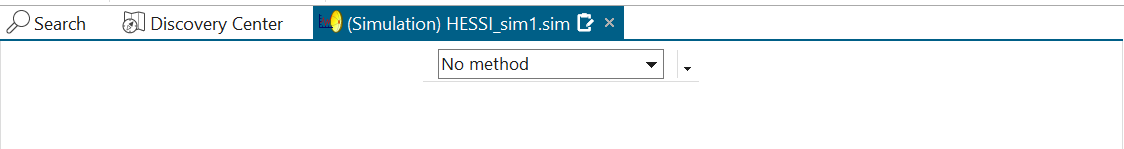
- Right-click the (Simulation) HESSI_sim1.sim window tab and choose Maximize.
-
In the Quick Access toolbar, from the
Window
list, select Reset
Layout
 to display all window tabs for opened
files.
to display all window tabs for opened
files.
Explore the ribbon bar
The Ribbon bar is located below the Quick Access toolbar. It contains tabs and commands. The tabs let you access groups of commands. The commands displayed under the Home tab depend on work part file type.
-
From the Quick Access toolbar, from the
Window
list, choose any FEM file.
-
Click the Home tab on the Ribbon bar.
The commands displayed for the FEM are different than those for the Simulation file. The commands are organized by groups, such as the Properties group.

-
In the Properties group, click Mesh
Collector
 .
.
- Click OK.
- You have created an empty mesh collector.
- In the Properties group, click the More list and explore additional commands in this group.
- Click the (Simulation) HESSI_sim1.sim tabbed window to make it the work part.
Use the command finder to locate commands
You will hide the frame of the structure using the command finder and QuickPick.
-
In the upper right corner of the Pre/Post window, click the Command
Finder.

- In the box, type Hide and press Enter.
-
From the list, select View all results for
"Hide".
The Command Finder dialog box lists commands that contain the word Hide and describe the location of these commands.
- Choose Hide (CTRL+B).
- In the Top border bar, set the Type Filter to Polygon Body.
-
Hover over the frame geometry as shown on the image and click after the
cursor changes to QuickPick
 indicator.
- From the list, select Polygon Body in FRAME_STRUCT_FEM1 that highlights
the rod as shown.
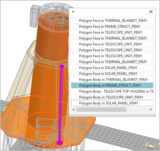
- Click OK.
Use the Simulation Navigator to work with your model
The Simulation Navigator
![]() presents the file relationships and analysis data in your
CAE model as a graphical, interactive, and hierarchical tree.
presents the file relationships and analysis data in your
CAE model as a graphical, interactive, and hierarchical tree.
- In the Simulation Navigator, expand HESSI_thermal_assyfem1.afm and explore the assembly FEM structure.
-
Hide
 the
thermal_blanket_fem1.fem to hide it in the
graphics window.
the
thermal_blanket_fem1.fem to hide it in the
graphics window.
-
Expand the frame_struc_fem1.fem→Polygon
Geometry nodes and show
 the Polygon Body (16) to
show the frame that you hid in the previous step.
the Polygon Body (16) to
show the frame that you hid in the previous step.
Use the Top Border bar to select and display items in the graphics window
The Top Border bar contains commands that let you select and control the display of items in the graphics window.
- In the Top Border bar, from the Type Filter list,
select Polygon Edge.

- In the graphics window, move your mouse over the model.
- Notice that only the polygon edges highlight.
Use the selection method in the scene toolbar
Use the Method list in the scene toolbar to select related entities easily and more efficiently.
- In the Simulation Navigator, right-click the Load Container node→New Load→Thermal Loads.
- Notice that in the scene bar the Method selection appeared.
-
In the Simulation Navigator, under the
HESSI_thermal_assyfem1.afm node, expand the
solar_panel_fem1.femx4 node and click to display the 2D mesh of the
solar panels.
- In the scene toolbar, from the Method list, select Attached Elements.
- Select any element on the solar panel.
- The software selects all connected elements.
-
In the scene toolbar, next to the
Method list, click Smart Selector
Options
 to specify criteria.
-
In the Smart Selector Options dialog box, select the
Limit Iterations
 check box.
- Click OK.
- Select any element on the solar panel.
- Notice that only connected elements are selected.
- Click Cancel.
Control display of your model
Change the display and orientation of the model and save your work part.
- Right-click in the background of the graphic window and choose Display Style→Wireframe.
- Right-click in the background of the graphic window and choose Orient View→Top.
- Try using some of the other commands to change the display and orientation of the model.
-
Click Save
to save the work part.