Selecting objects
Practice selecting objects using different methods such as QuickPick, creating groups, and a selection recipe.
Open the Simulation file
Open the Simulation file and reset the dialog box settings.
- Choose File→Open and open capacitor/capacitor_inquiry_sim.sim.
- Choose File→Preferences→User Interface and on the Dialog and Precision page, reset the dialog box memory.
- Click OK.
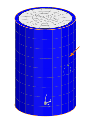
Select faces using QuickPick
Select faces using QuickPick.
- In the Top border bar, set the Type Filter to Polygon Face.
-
Move the mouse over the face of the model.
-
Wait until three dots show up near the cursor, then click to open the
QuickPick list.
Tip: If the three dots do not display, you need to activate QuickPick. Search for QuickPick. In the Selection Preferences dialog box, in the QuickPick group, enable QuickPick on Delay and click OK.
-
Move the cursor over each item in the QuickPick
list, and notice which entities are highlighted in the graphics
window.
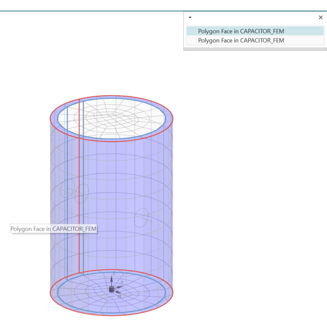
- From the QuickPick list, select one of the faces.
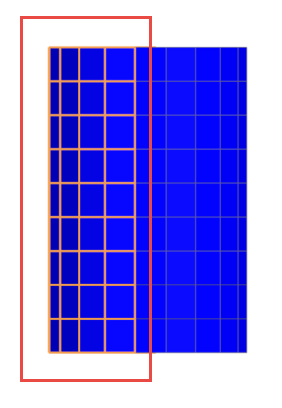
Create the Bounding Volume selection recipe
Create a selection recipe that will enable you to select all faces within a defined area.
- In the Simulation Navigator, right-click the Selection Recipes node and choose New Selection Recipe.
- In the Type group, from the Strategy list, make sure that Bounding Volume is selected.
- In the Entity Types group, select the Polygon Face check box.
- In the Bounding Volume Definition group, from the Method list, keep Box - CSYS and Edge Lengths to create a box using the origin of the selected coordinate system to define the size of the box.
-
Set the following coordinates:
- X=-10
- Y=-10
- Z=-1
- Press Enter.
-
In the Dimensions group, set the following:
- Length (XC)=20 mm
- Width (YC) = 20 mm
- Height (ZC) = 4 mm
- Click OK.
- In the Simulation Navigator, under the Selection Recipes node, right-click Selection Recipe and select Show Contents Only to display only defined faces.
-
Choose Home tab→Visibility
group→Show and Hide
 .
.
-
In the Show and Hide dialog box, under
CAE Entities, next to
Meshes, click
 to display the meshed body.
- Click Close.
Use the selection recipe to specify a boundary condition
Use a selection recipe to identify where the free convection will be applied.
-
Choose Home tab→Loads and
Conditions group→Constraint Type
list→Convection to Environment
 .
.
- Select the Free Convection to Environment type.
- In the Name box, type bottom convection.
-
In the Region group, click Select
Object
 .
.
-
In the Simulation Navigator, under the
Selection Recipe node, click
SelectionRecipe.
Notice the area that is selected.
- In the Parameters group, from the Correlation list, select Horizontal Plate.
- Click OK.
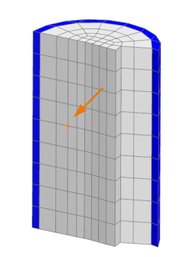
Examine internal elements
Expose or examine internal elements and know their nodes and element numbers.
- Rotate the model to closest orthogonal view by pressing F8.
- In the Top border bar, set the Type Filter to Element.
-
Select half the elements of the capacitor.
-
Choose Home tab→Visibility
group→Show Only
 to display internal elements.
- Click OK.
- In the Top border bar, set the Type Filter to Node.
-
Choose Home tab→Checks and
Information group→Node/Element
 to display the information about the selected
node.
to display the information about the selected
node.
-
Select the shown node or any node.
- Make sure that the Retain Label Visibility After Dialog Closes check box is selected to keep the node displayed on your model once you close this dialog box.
-
Click OK.
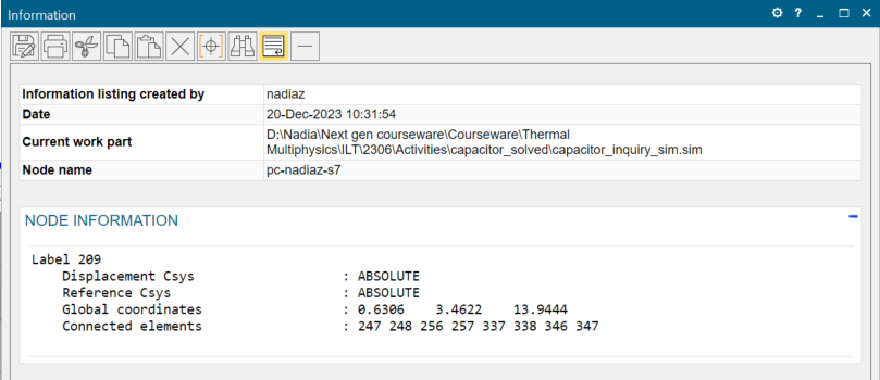
The Information window displays the node number, its coordinates, and the connected elements. Remember the number of connected elements. The numbers that are displayed may be different. - Close the Information window.
Create a group with specific elements
Use the manual group creation method to create a new group of specific elements.
- In the Simulation Navigator, right-click the Groups node and select New Group.
- In the Element Labels subgroup, type any connected element label, for example 247.
-
Click Select
 .
.
- In the Name and Label group, next to Name, type element-247.
- Click OK.
- In the Simulation Navigator, under the Group node, right-click 1-element-247 and select Show Only.
-
Choose Home tab→Visibility
group→Show Adjacent
 .
.
- Select the displayed element.
- Click OK.
- In the Simulation Navigator, right-click the Groups node and select New Group to create a group of adjacent elements.
- In the Top border bar, set the Type Filter to Element.
- Select all displayed elements.
- Next to Name, type adjacent elements.
- Click OK.
Solve the model
Solve the model.
- In the Simulation Navigator, right-click the Solution 1 node and choose Solve.
-
Click OK.
The solution takes less than 2 minutes to solve. When the solution is complete, the Analysis Job Monitor displays the status as Completed Successfully.
- In the Review Results dialog box, click No.
- Close the Information window.
- In the Analysis Job Monitor dialog box, click Cancel.
Inquire temperatures on groups of elements
Display the temperature on specific elements.
- In the Post Processing Navigator, double-click Thermal to load the results.
- Expand the Thermal node and double-click Temperature-Elemental.
-
Choose Results tab→Tools
group→Identify Results
 .
.
- From the Element Results list, select Elements in Group.
- From the Group list, select element-247.
-
Click Apply Group
.
Notice the temperature on the element.
- Click Close.
- In the Post Processing Navigator, expand the Post View 1 node, under the Groups node, right-click the adjacent elements and select Show Only to display the temperature of the adjacent elements.