Use a user written subroutine to define a thermostat
Practice defining a thermostat using an alternative method such as including a DLL file generated from a user-written subroutine to the power supply model.
Explore a user-written subroutine
Locate the USER1.f subroutine in the user_subroutine\USER1 folder. You will use the USER1 subroutine to simulate a thermostat with a time varying heat load on the diode. The thermostat turns on when the temperature is lower than 45 °C, and shuts down once it reaches 50 °C. The heat load reaches 5 W after 10 seconds. The subroutine uses a generic entity that contains the following modeling data: the heater and sensor elements, the cut off and cut in temperatures, the heat load, and the heating time.
-
Open USER1.f in a text editor and explore it.
The standard USER1 header must be included. Make sure that you do not modify it.
SUBROUTINE USER1(GG,T,C,Q,QD,R,TIME,DT,IT,KODE,NOCON,MAXNO, +ICONV,DUM1,DUM2,DTP,TF) IMPLICIT NONE C --- ARGUMENTS DOUBLE PRECISION T(*), TIME, DT REAL GG(*), C(*), Q(*), QD(*), R(*) REAL DUM1, DUM2, DTP, TF INTEGER IT, KODE, NOCON, MAXNO, ICONV(*) C --- COMMON BLOCK VARIABLES REAL TDMAX, PRTFLG, PARAMS(8000), GRAV, GV(3), TABS, RGAS REAL PSTD, TSTD, SIGMA INTEGER IRUN, IR(1), MAXN1, MAXN2 C --- COMMON BLOCK DEFINITIONS COMMON/TDMAX/TDMAX COMMON/PRTFLG/PRTFLG COMMON/IRUN/IRUN,IR COMMON/MAXNOQ/MAXN1,MAXN2 COMMON/PARAMS/PARAMS COMMON/GRAV/GRAV,GV,TABS,RGAS,PSTD,TSTD,SIGMA -
The following predefined subroutines are included:
- GENERIC returns the parameters associated with Card 9 - GENERIC whose ID is N1. This card defines a set of generic entities for the model.
- GENERICINDEX returns the external index of a generic entity for the given internal index.
- NAMAR returns a list of elements in a group.
-
The time varying heat load is set as follows:
IF(TIME.LT.HEAT_TIME.AND.HEAT_TIME.NE.0.0) THEN HEAT_LOAD=HEAT_LOAD*TIME/HEAT_TIME ENDIF -
Thermostat rules are applied as follows:
Apply thermostat rules: C IF (TAVG.LT.CUT_IN_TEMP) THEN C C Temperature has fallen below Real 2, turn on heat C DO I=1,NGRP1 Q(ELEMS_IN_GRP1(I))=HEAT_LOAD/REAL(NGRP1) ENDDO C ELSE IF (TAVG.GT.CUT_OFF_TEMP) THEN C C Temperature above Real 1, turn off heat C DO I=1,NGRP1 Q(ELEMS_IN_GRP1(I))=0.0 ENDDO ENDIF -
Note that a dummy USERF subroutine is included at the end of the file.
      SUBROUTINE USERF(GG,T,C,Q,QD,R,TIME,DT,IT,KODE,NOCON,MAXNO,
     +ICONV,DUM1,DUM2,DTP,TF)
      RETURN
      END
It is required only when the file is precompiled in the following step. If the compilation is performed at run time, the solver automatically generates it.
Compile user-written subroutine (Optional)
If you have a FORTRAN compiler on Windows, you can generate the DLL file form USER1.f using the createUserDll.cmd script.
- Locate the createUserDll.cmd file in the [installation_path]\nxcae_extras\tmg\exe.
- Copy createUserDll.cmd to the folder containing the USER1.f file that is separate from the running directory.
- Specify the UGII_TMG_DIR and SDRC_TMG environmental variables to the [installation_path]\nxcae_extras\tmg.
- Open a Command Prompt from the start menu.
- In the command prompt window, browse to the directory containing the USER1.f file and run the createUserDll.cmd file.
-
Open the createUserDll.cmd script in any text editor, and edit
the script to specify the correct compiler.
The script compiles the user-written subroutine USER1 and generates the DLL file called tmgopen.dll.
-
For the thermal solver to use this DLL during the solution process, you must rename
it to tmgopen_user.dll and place it in your run directory.
For your convenience, the tmgopen_user.dll file is provided in the USER1 folder. You do not need to compile the USER1.f file.
Open the Simulation file
Open the model Simulation file and reset the dialog box settings.
- Choose and open part_files\user_subroutine\powersupply_sim.sim.
- Choose and on the Dialog and Precision page, reset the dialog box memory.
Define generic entity
Create a generic entity to define modeling data that the subroutine uses.
-
Choose
 .
.
- From the type list, select Generic Entity.
- In the Name group, type Thermostat data.
- On the scene toolbar, from the Method list, select Related Elements.
- On the Top Border bar, from the Type Filter list, select Polygon Body.
-
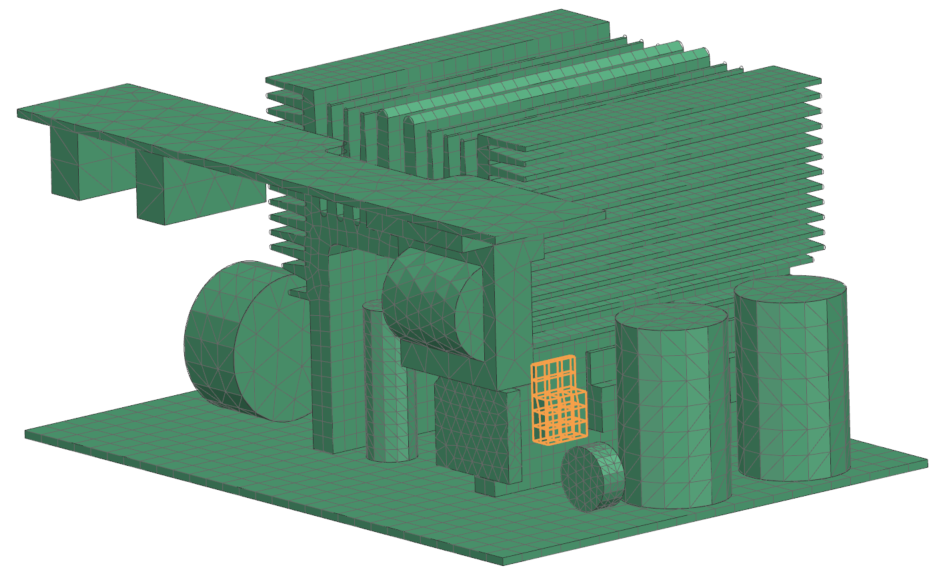
In the graphics window, select the element as shown to set the heater elements.
-
In the Set 2 Region group, click Select Object
 .
.
- Set 2 region contains the sensor elements. The selection for the Set 2 is the same as for the Set 1 because the sensor region is the same as the heater region.
-
In the Text Options tab, in the Type box, type Time Variable Heater Control.
Notice that the type you set for advanced control text option must be the same as in the subroutine.
IF (STR1(1:28).EQ.'Time Variable Heater Control') THEN C This is for clarity CUT_OFF_TEMP=RARR(1) CUT_IN_TEMP=RARR(2) HEAT_LOAD=RARR(3) HEAT_TIME=RARR(4) - In the Real Values tab, in the Real 1 box, type 50 to indicate the cut off temperature in °C.
- In the Real 2 box, type 45 to indicate the cut in temperature in °C.
- In the Real 3 box, type 5e6 to indicate the heat load in microwatts.
- In the Real 4 box, type 10 to indicate the heating time in seconds.
- Click Apply.
Define advanced parameter
Create an advanced parameter to activate the user DLL scheme for user-written subroutine.
- From the type list, select Advanced Parameter.
- In the Name group, enter User DLL.
-
In the Parameter Definition group, click Catalog
 .
.
- From the Item list, expand the nodes and select the ACTIVATE USER DLL SCHEME node.
- Click OK on both dialog boxes.
Solve the solution
- In the Simulation Navigator, right-click the Solution 1 node and choose Solve.
- Click OK.
- Wait for the solve to end, before proceeding.
- In the Review Results dialog box, click No.
- Close the Information window.
- In the Analysis Job Monitor dialog box, click Cancel.
Review results
Plot the temperature history of a node to show the behavior of the thermostat over time.
- In the Post Processing Navigator, right-click the Thermal node and choose Load.
- Expand the nodes and double-click the Temperature - Nodal node.
-
Choose
 .
.
- From the type list, select Across Iterations.
-
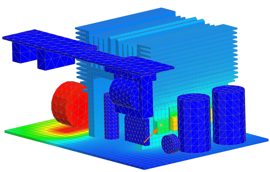
In the graphics window, select the node as shown.
- Click OK.
-
Click in the graphics window.
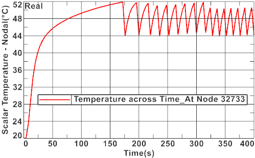
Notice the behavior of the thermostat with time-varying heat load. The oscillation in temperature is the nature of thermostats. You may use a PID Active Heater Controller modeling object to create a logic-driven thermostat, which controls thermal loads and suppresses the temperature variations.