Troubleshoot the model
Practice troubleshooting the model. The model has two issues: missing thermo-optical properties of some parts and an incomplete radiation request. You will identify and resolve these issues. You will also learn how to solve a thermal analysis using parallel processing and you will understand how to modify properties on selected elements and deactivate elements without modifying the FEM file.
Open the Simulation file
Open the Simulation file, reset dialog box settings, and explore the model.
- Choose File→Open and open oven\oven_sim1.sim.
- Choose File→Preferences→User Interface.
-
On the Dialog and Precision page, click
Reset Dialog Memory
 .
.
- Click OK.
-
In the Simulation Navigator, explore the defined
boundary conditions:
- Inner to Outer Walls thermal coupling with HTC= 6 W/m2·°C.
- Bottom to Pyrex Pot thermal coupling with HTC = 2 W/m2·°C.
- Convection from Oven Sides constraint use an inclined plate convection correlation.
- Convection from Oven Top constraint use a horizontal plate convection correlation.
- Radiation to Environment from Oven Walls constraint with the radiative ambient temperature.
- Filament temperature constraint is set to 2000 ºC.
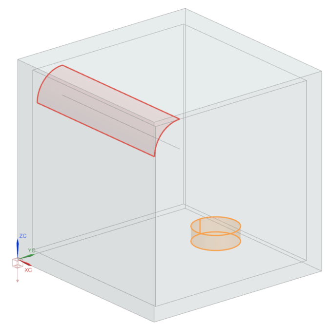
- Radiation Request Inside Oven simulation object: for the Top Side Region, 9 faces are selected (6 inner faces of the oven, 2 faces of the pot, and the filament face) and for the Bottom Side Region, 3 pot faces are selected. Observe that the Elements not Part of this Enclosure Can Shadow check box is selected. This means that even if a section of your model is not included in the radiation request, it will be included in the radiation calculation for shadowing checks. This can be useful for complex geometries, but it requires additional processing time.
Set the parallel processing parameters
Set the parallel processing parameters to reduce solve time. Your computer cores communicate during the run using Platform MPI.
- In the Simulation Navigator, right-click Solution 1 and choose Edit Solver Parameters.
- In the Parameters group, on the Thermal/Flow Solver tab, select Run Solution in Parallel.
-
In the Parallel Configuration File group, click Create New File.
If an MPI registration window appears, enter your username and password.
- In the Enable Parallel window, select the View Factors check box.
- In the Settings window, in the No. processes for View Factors,type 3.
-
In the New Parallel Configuration File.xml dialog
box, choose File→Save As,
navigate to the solution folder and click Save.
Keep the proposed name: Parallel Configuration File.xml.
- Close Parallel Configuration Tool.
- Click OK
Solve the model
Solve the model and monitor completion status.
- In the Simulation Navigator, right-click Solution 1 and choose Solve.
- Click OK and wait for the status to display Completed in the Analysis Job Monitor.
- In the Review Results dialog box, click No.
- Close the Information window.
- In the Analysis Job Monitor dialog box, click Cancel.
Display results
Visualize the nodal temperature results inside the oven.
- In the Simulation Navigator, expand Solution 1 node and double-click the Results node.
- In the Post Processing Navigator, expand Thermal and double-click Temperature-Nodal.
-
Expand the Post View 1→oven_fem1.fem→2D Elements nodes, clear 2D Elements and select Inside Oven Walls.
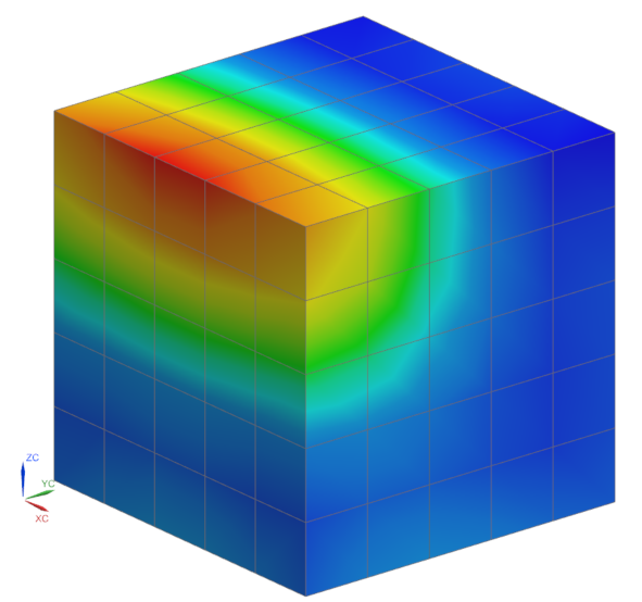
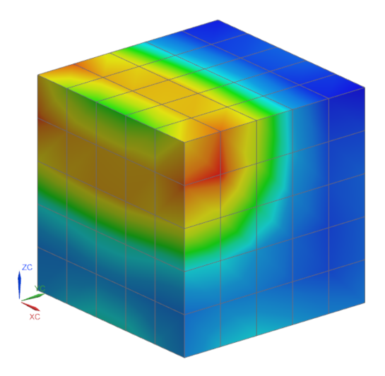
The temperature inside the oven varies between ~210 ºC to ~311 ºC. The radiation from the filament seems to fall directly on the walls of the oven, therefore the reflector is not shadowing the filament radiation.
Modify the thermal-optical properties for the reflector
Verify and modify the reflector's thermal properties. In the last step, you saw that although the reflector was meshed, it did not shadow the thermal radiation.
-
Choose Results tab→Context
group→Return to Home
 .
.
- In the Simulation Navigator, right-click oven_fem1.fem and choose Make Work Part.
- Expand the oven_fem1.fem → 2D Collectors nodes, right-click Reflector and select Edit.
- In the Thermo-Optical Properties group, from the Radiation list, select Top to define emissivity for modeling radiation.
- Next to Top, click Open Manager
- In the Create group, click Create.
- In the Modeling Object group, in the Name box, type Polished Aluminum Top.
- In the Properties group, in the Emissivity box, type 0.1.
- Click OK.
-
In the List group, click Add
 .
.
- Click Close.
- Click OK in all dialog boxes.
- In the Simulation Navigator, expand the Reflector node, right-click the reflector mesh node, and choose Check→Element Normals to verify if the thermo-optical properties were applied on the right surfaces. Element normal direction defines the thermo-optical properties side.
-
Click Display Normals.
Notice that the normals are pointing outside. The normals must point inside for this case.
- In the Method group, select Orient Normals to change the orientation of element normals.
- In the Orientation Method group, make sure that Using Seed Element is selected.
- In the Simulation Navigator, clear Polygon Geometry check box and select the reflector mesh check box to display the reflector's mesh.
- In the graphics window, select any mesh element.
- In the Seed Element group, select the Reverse Normal check box to reverse the normal of the selected seed element.
-
Click Align Normals to change the orientation of the
selected elements to match the orientation of a seed element.
- Click Close.
Solve the modified model and display results
Solve the model, review warnings, and visualize temperature distribution changes.
- In the Simulation Navigator, double-click the oven_sim1.sim node to make the Simulation file active.
- In the Simulation Navigator, right-click the Solution 1 node and choose Solve.
- Click OK.
- In the Review Results dialog box, click Yes.
-
Inspect the Simulation Monitor and locate the
WARNINGmessages. -
Examine the messages in the Solution Monitor dialog
box.
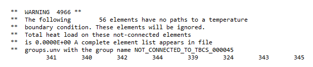
The warning message indicates that 56 elements are not thermally connected to the boundary conditions of the model.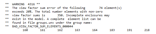
The warning message indicates that the radiation enclosure in the model is not complete.
- Close the Information window and log file.
- In the Analysis Job Monitor dialog box, click Cancel.
- In the Simulation Navigator, double-click the Results node.
- Under the Thermal node, double-click the Temperature-Nodal node.
-
Expand the Post View
2→oven_fem1.fem→2D
Elements nodes,clear 2D Elements and
select Inside Oven Walls.
Notice that the temperatures changed. Shadowing is visible on the upper edge of the filament side, but temperatures are still too high.
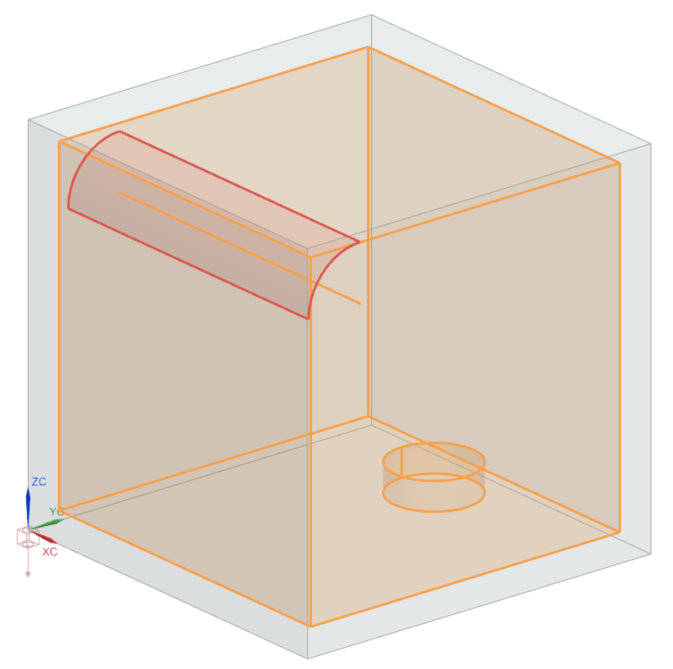
Include the missing face to the radiation request
The mesh affected by the radiation request must contain the 120 elements mentioned in the warning, but they are not currently included in its definition. Examine radiation inside the oven and include a missing surface.
-
Choose Results tab→Context
group→Return to Home
.
- In the Simulation Navigator, select the Polygon Geometry check box and clear the 2D Collectors check box.
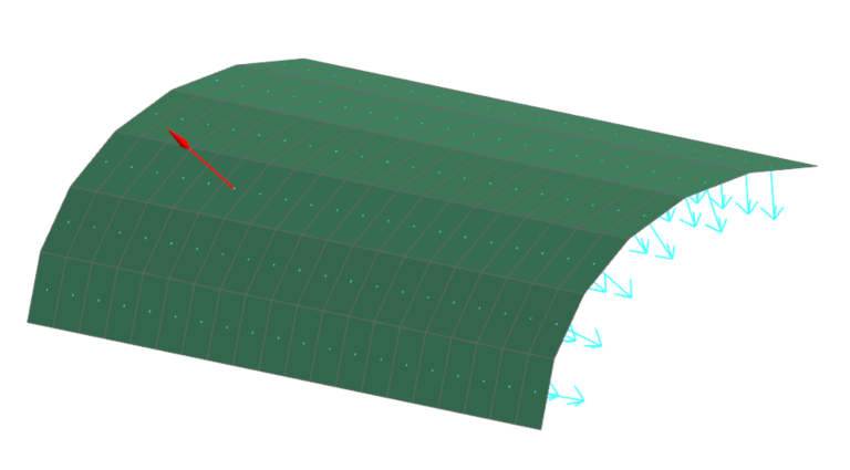
- Under the Simulation Objects node, right-click Radiation Request Inside Oven and choose Edit.
-
In the Top Side Region group, click
Select Object and in the graphics window using
QuickPick, select the reflector's face shown in
red.
- Click OK.
- In the Simulation Navigator, right-click the Solution 1 node and choose Solve.
- Click OK.
- In the Review Results dialog box, click Yes.
-
Examine the messages in the Solution Monitor dialog
box.
Notice that the warning 4966 has disappeared, the reflector elements have now been thermally connected. The warning 4316 is still present, however, the number of elements of which the view factor sum error exceed 20 % decreased to 32 elements. There is a new warning:
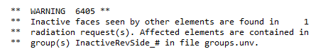
The warning message indicates that there are inactive faces seen by other elements in the radiation request. - Close the Information window and log file.
- In the Analysis Job Monitor dialog box, click Cancel.
- In the Simulation Navigator, double-click the Results node.
- Under the Thermal node, double-click the Temperature-Nodal node.
-
Expand the Post View
3→oven_fem1.fem→2D
Elements nodes,clear 2D Elements and
select Inside Oven Walls .
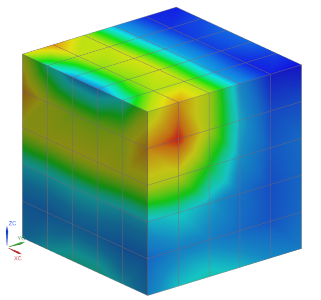
Notice how the temperature has changed. The reflector elements are now thermally connected to the model. Shadowing is visible but the temperature is still high.
Include the bottom side of the reflector to the radiation
The warning message about inactive faces seen by other elements in the radiation request means that if you post-process the radiosity or irradiance flux on the bottom side of the reflector elements, they will all be zero. Include the bottom side of the reflector to the radiation request, since it must also be incident and radiated.
-
Choose Results tab→Context
group→Return to Home
 .
.
- In the Simulation Navigator, right-click the oven_fem1.fem node and choose Make Work Part.
- Under 2D Collectors, right-click the Reflector node and choose Edit.
- In the Properties group, click Edit .
- In the Thermo-Optical Properties group, from the Radiation list, select Top and Bottom.
-
Next to Bottom, click Open
Manager
 .
.
- Click Create.
- In the Name box, type Polished Aluminum Back.
- In the Properties group, in the Emissivity box, type 0.8.
- Click OK.
- In the List group, click Add.
- Click Close.
- Click OK in all dialog boxes.
- In the Simulation Navigator, double-click the oven_sim1.sim node to make the Simulation file active.
- In the Simulation Navigator, under the Simulation Objects node, right-click Radiation Request Inside Oven and choose Edit.
-
In the Bottom Side Region group, click Select Object and using QuickPick, select the reflector's face shown in red.
- In the Parameters group, clear the Element not Part of this Enclosure Can Shadow check box since thermo-optical properties and radiation enclosure were corrected.
- Click OK.
- In the Simulation Navigator, right-click the Solution 1 node and choose Solve.
- Click OK.
- In the Simulation Navigator, double-click the Results node.
- Under the Thermal node, double-click the Temperature-Nodal node.
-
Expand the Post View
4→oven_fem1.fem→2D
Elements nodes, hide 2D Elements and
show Inside Oven Walls.
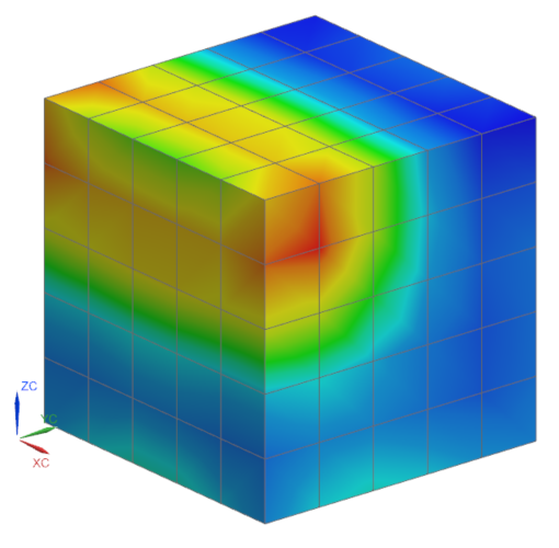
Notice that the temperature has decreased, and there has been a change in the temperature distribution. This alteration is due to radiation on the bottom side of the reflector.
Import solution warnings
Import solution warning groups and observe highlighted elements.
-
Choose Home tab→Context
group→Return to Home
.
- Choose File tab→Import→Simulation.
- From the Select Solver list, select Simcenter 3D Thermal/Flow.
- Click OK.
- From the File Type list, select Solution Error/Warning Groups.
- In the Input File row, click Browse.
- Select the groups.unv file from the run directory.
- Click OK on both dialog boxes.
- Close Information window.
- In the Simulation Navigator, expand Groups and choose 3 - BAD_VIEW_FACTOR_SUM_ELEMENTS_000045.
-
Under the 2D Collectors, select the
Inside Oven Walls check box and observe the highlighted
elements.
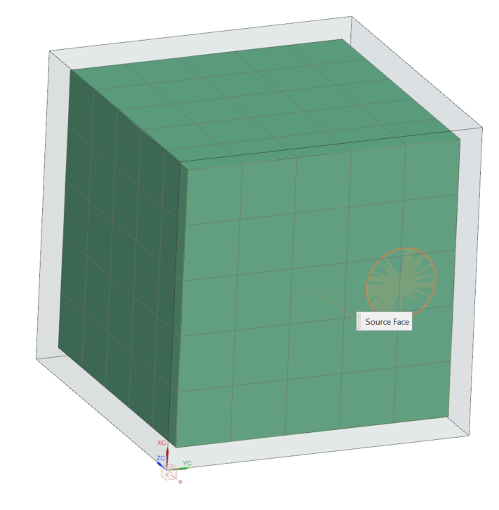
Create the mesh mating between the inside oven wall and Pyrex pot
Resolve bad view factor sum elements by creating identical meshes for contact definition since the pot is directly on the oven's wall.
- In the Simulation Navigator, right-click the oven_fem1.fem node and choose Make Work Part.
- Right-click the oven_fem1_i.prt node and choose Load.
-
Choose Home tab→Connections
group→Mesh Mating
 .
.
- Select the Manual Creation method.
-
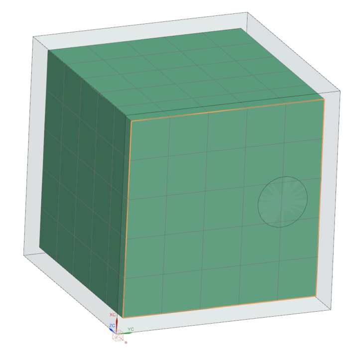
Click Select Source Face and in the graphics window
select the shown face.
-
Click Select Target Face and in the graphics window
select the shown face.
- Click OK.
-
Choose Home tab→Context
group→Update
 .
Notice that the imported group does not have entities anymore.
.
Notice that the imported group does not have entities anymore. - Under the Groups node, right-click 3 - BAD_VIEW_FACTOR_SUM_ELEMENTS_000045 and select Delete.
- In the Simulation Navigator, double-click the oven_sim1.sim node to activate the Simulation file.
- In the Simulation Navigator, under the Solution 1 node, right-click the Bottom to Pyrex Pot node and select Remove to exclude the thermal coupling between the wall and pot since the mesh mating is created.
- In the Simulation Navigator, right-click the Solution 1 node and choose Solve.
- Click OK.
- In the Review Results dialog box, click Yes.
-
Examine the messages in the Solution Monitor dialog box.
No warnings are displayed regarding the bad view factor sum elements.
- In the Simulation Navigator, double-click the Results node.
- Under the Thermal node, double-click the Temperature-Nodal node.
-
Expand the Post View 4 →
oven_fem1.fem → 2D
Elements nodes, clear the 2D Elements
check box and select the Inside Oven Walls check
box.
Notice that the temperature is the same as in the previous case.
Override thermal conductivity of selected elements
This step shows how to modify the thermal conductivity of the elements at the center of the reflector without modifying the FEM file. You have two alternatives:
- Use a Mesh Collector override to modify properties on all elements from the mesh collector.
- Use an Override Set - Thermal Properties simulation object to modify properties on selected elements.
In this activity, you will use Override Set - Thermal Properties, where you will modify the thermal conductivity from 205 W/m-K, which is the thermal conductivity of the Oven Aluminum material to, for example, 0.01 W/m-K.
- In the Simulation Navigator, right click Solution 1 and choose Clone.
- Right-click the Copy of Solution 1 node, choose Rename and type overridden thermal conductivity.
- In the Simulation Navigator, clear the Inside Oven Walls check box and select the Reflector check box to display the reflector's mesh.
-
Choose Home tab→Loads and
Conditions group→Simulation Object
Type list→Override Set - Thermal
Properties
 .
.
- Make sure that the Thermal Conductivity type is selected.
- In Top border bar, set the Type Filter to Element.
-
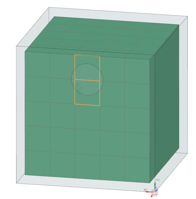
In the graphics window, select the four central element columns.
Tip: Press F8 to have the shown model orientation.
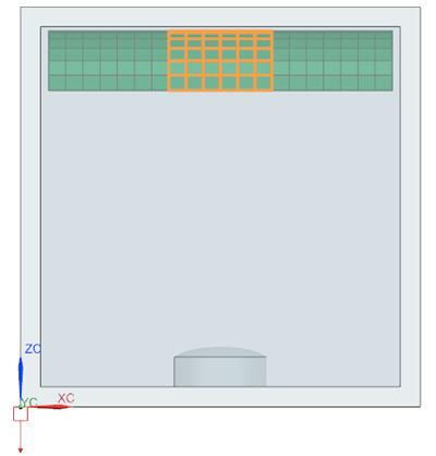
24 elements are selected.
- In the Magnitude group, in the Thermal Conductivity box, type 0.01 W/(m·dK).
- Click OK.
- In the Simulation Navigator, right-click the overridden thermal conductivity node and choose Solve.
- Click OK.
- In the Review Results dialog box, click No.
- Close the Information window.
- In the Analysis Job Monitor dialog box, click Cancel.
- In the Simulation Navigator, double-click the Results node.
- Under overridden thermal conductivity→Thermal node, double-click the Temperature-Nodal node.
- Expand the Post View 5→oven_fem1.fem→2D Elements nodes, clear the 2D Elements check box and select the Reflector check box.
- Choose Results tab→View Layout group→Layout Drop-down→Side by Side to display the temperature results from the overridden thermal conductivity solution in the left viewport of the graphics window and the temperature results of the Solution 1 in the right viewport.
- Under the Solution1 node, double-click the Temperature-Nodal node and select the right viewport.
-
Expand the Post View 6→oven_fem1.fem→2D Elements nodes, clear the 2D Elements check box and select the Reflector check box.
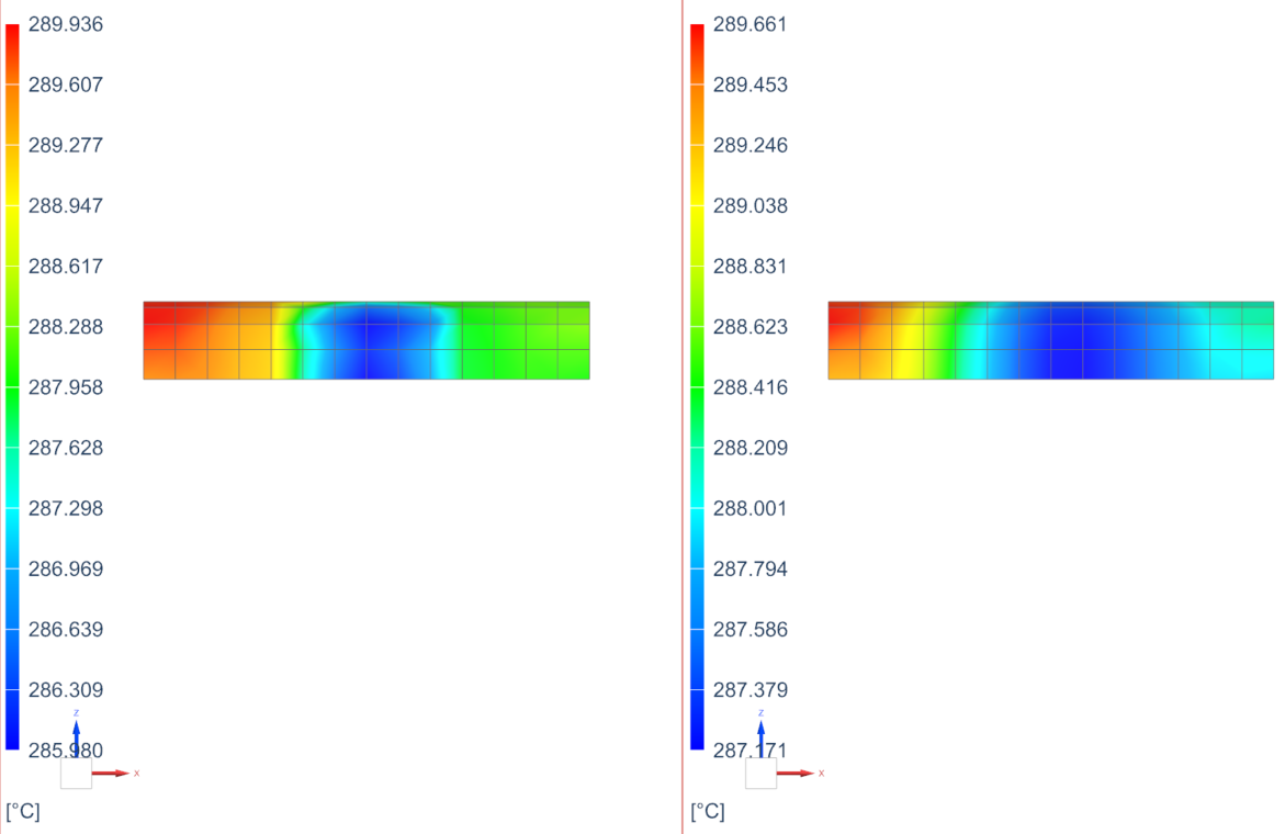
Observe how the temperature distribution on the elements on which you modified the thermal conductivity has changed. A decrease in thermal conductivity means that the material will be less efficient at conducting heat. As a result, heat transfer within the material will slow down, leading to higher temperatures in certain regions and potentially lower temperatures in others. -
Choose Results tab→View
Layout group→Layout
Drop-down→Single View
 .
.
Deactivate elements on the reflector
This step shows how to deactivate elements on the reflector without deleting them from FEM. The thermal solver ignores the deactivated elements while performing the calculations related to the selected option.
-
Choose Results tab→Context
group→Return to Model
.
-
Choose Home tab→Loads and
Conditions group→Simulation Object
Type list→Deactivation Set Advanced
 .
.
- In Top border bar, set the Type Filter to Element.
-
In the graphics window, select the six central element columns.
- In the Deactivation Options group, select the Eliminate from Solution check box.
- Click OK.
- In the Simulation Navigator, right-click the overridden thermal conductivity node and choose Solve.
- Click OK.
- In the Review Results dialog box, click No.
- Close the Information window.
- In the Analysis Job Monitor dialog box, click Cancel.
- In the Simulation Navigator, double-click the Results node.
- Under overridden thermal conductivity → Thermal node, double-click the Temperature node.
-
Expand the Post View 1→oven_fem1.fem→2D Elements nodes, clear the 2D Elements check box and select the Reflector check box.
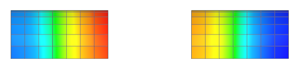
Notice that the elements you selected were removed from the solution.