Define a thermostat in a steady state solution
Practice defining a Thermostat modeling object in a steady state solution.
Open the Simulation file
Open the model Simulation file and reset the dialog box settings.
- Choose File→Open and open power_supply_steady_state\powersupply_sim.sim.
- Choose File→Preferences→User Interface.
-
On the Dialog and Precision page, click
Reset Dialog Memory
 .
.
- Click OK.
Define a thermostat
Define a thermostat for one of the 5 W heat loads applied on a diode. The thermostat turns on when the temperature is lower than 50 °C and shuts down once it reaches 56 °C.
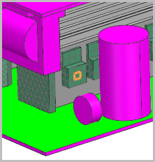
- In the Simulation Navigator, expand the Load Container→thermal_loads nodes and observe the thermal loads applied to diodes and coils.
- Right-click the diode heat load 5W(2) node and choose Edit.
- In the Heater Control group, select the Control Heater check box.
-
In the Heater Controller or Thermostat row, click
Open Manager
 .
.
- In the Create group, from the Type list, select Thermostat.
- Click Create.
- In the Simulation Navigator, expand the powersupply_fem.fem→3D Collectors nodes and select the diodes collector check box to show related elements in the graphics window.
- On the Top Border bar, from the Type Filter list, select Element.
-
In the graphics window, select the following element on the diode to place
the sensor.
-
In the Control group, set:
- Cut-in Temperature = 50 ºC
- Cut-off Temperature = 56 ºC
- Click OK.
-
In the List group, click Add
 .
.
- Click Close and OK.
Create a steady state solution and add the boundary condition
Create a steady state solution and control thermostat modeling object; add existing boundary conditions.
- In the Simulation Navigator, right-click the powersupply_sim.sim node and choose New Solution.
- In the Name box, type Steady State Solution.
-
From the Solver list, select one of the following: Simcenter 3D Thermal/Flow, Simcenter 3D Electronic Systems Cooling, Simcenter 3D Space Systems Thermal, or Simcenter 3D Multiphysics.
Note that for this activity the Simcenter 3D Electronic Systems Cooling solver is selected and Coupled Thermal-Flow analysis.
- Click Create Solution.
- On the Solution Details page, in the Solution Type group, make sure that Steady State is selected.
-
On the Solution Details page, in the
Solution Type group, verify that the
Thermostat list is set to Sink to Average
Temperature.
This option constrains the thermostat element at the average of the set point temperatures, that you specified on the sensor, in the steady state analysis.
- On the Initial Conditions page, from the Initial Conditions list, select Uniform.
-
Click OK.
No boundary condition is included in the solution.
- In the Simulation Navigator, expand the Simulation Object Container and Constraint Container nodes.
- Press Ctrl and select the thermal_couplings, Convection to Environment(1), and thermal_loads nodes.
- Right-click the selected nodes and choose Add to Active Solution or Step.
- Click Active Solution and Step.
Solve the solution
Solve the model and wait for completion.
- Right-click the Steady State Solution node and choose Solve.
- Click OK.
- Wait for the solve to end before proceeding.
- In the Review Results dialog box, click No.
- Close the Information window.
- Click Cancel in the Analysis Job Monitor dialog box.
Post Process the results
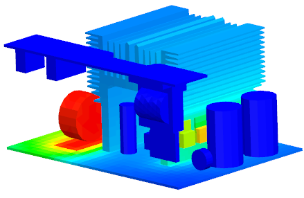
Visualize the temperature distribution on the elements.
- In the Post Processing Navigator, under the Steady State Solution node, right-click the Thermal-Flow node and choose Load.
- Expand the Thermal-Flow node and double-click Temperature - Elemental.
-
Choose Results tab→Display
group→Edge Style drop-down
list→None
 .
.
-
Choose Results tab→Tools
group→Identify Results
 .
.
-
Select the element on the diode where you placed the sensor.
Note that in the steady state solution, the sensor is kept at the average temperature.