Model Joule heating
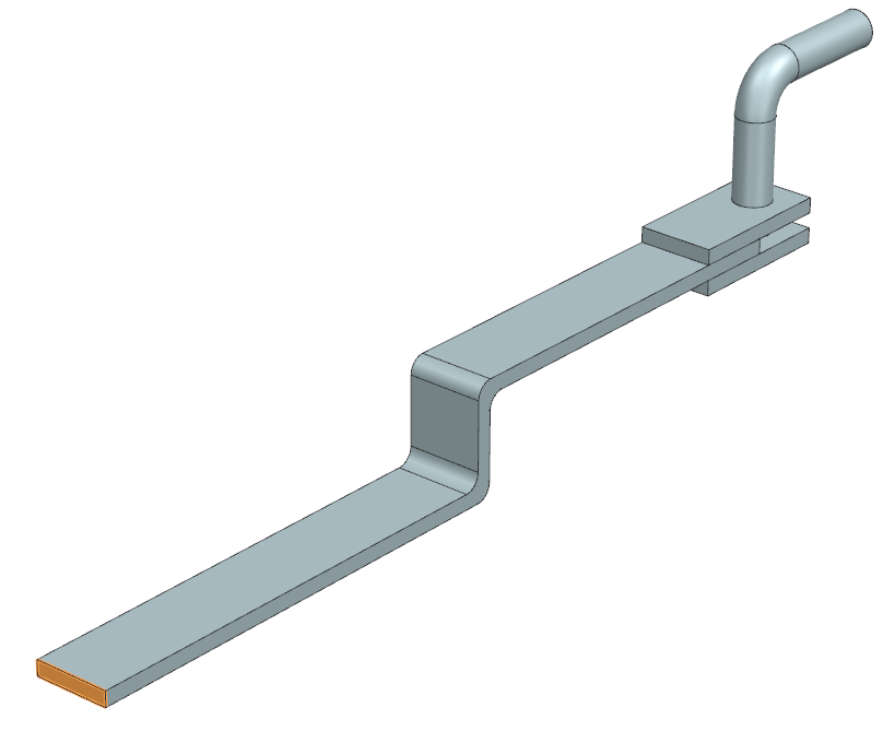
Practice modeling Joule heating of an electrical connector to study how electrical current in an electrical network affects temperature distribution in the model. You will create an electrical network by specifying the material's electrical resistivity and defining the electrical and thermal couplings of the electrical connector.
Open the Simulation file
Open the Simulation file and reset the dialog box settings.
- Choose File→Open and open joule_heating\Joule_Heating_sim1.sim.
- Choose File→Preferences→User Interface and on the Dialog and Precision page, reset the dialog box memory.
- Click OK.
Add temperature dependent electrical resistivity
Copy a material and add electrical properties from an external file to create a new material.
- In the Simulation Navigator, right-click the Joule_Heating_fem1.fem node and choose Make Work Part.
- Expand the Joule_Heating_fem1.fem → 3D Collectors nodes, right-click the Copper node and choose Edit.
-
In the Properties group, in the Solid
Property row, click Edit
 .
.
-
In the Properties group, in the
Material row, click Choose
material
 .
.
- In the Material List group, from the list, select Local Materials.
- In the Materials table, right-click Copper_C10100 and choose Clone.
- In the View group, from the list, select Isotropic.
- In the Name box, type Copper_Electrical.
-
On the Electromagnetic page, in the
Electrical Properties group, in the
Resistivity row, click
 and select New Field →
Table
and select New Field →
Table
 .
.
-
On the Definition page, click Import from
Text File
 .
.
- Click Browse, and select the Copper_Electric_Resistivity.txt text file.
-
Click OK.
Observe the electrical resistivity values at three different temperatures.
- Right-click the electrical resistivity (ohm-mm) row and select Change Units for Variable to switch to ohm-m since the table values are given in ohm-m.
- Click OK for all the dialog boxes.
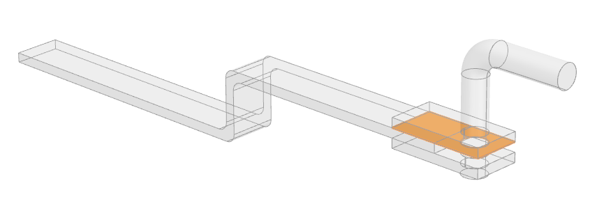
Define electrical boundary conditions
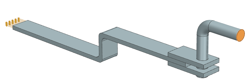
Create an electrical network by applying electrical boundary conditions to both ends of the model using the Joule Heating simulation object. You can specify either a voltage differential with two voltage sources, or a current source associated with a voltage source.
- In the Simulation Navigator, right-click the Joule_Heating_sim1.sim node and select Make Work Part.
- In the Simulation Navigator, hide 3D Collectors.
-
Choose Home tab→Loads and
Conditions group→Simulation Object
Type list→Joule Heating
 .
.
- In the Name group, type Current_BC.
- On the Top Border Bar, from the Type Filter list, select Polygon Face.
-
Select the highlighted surface of the electrical connector.
- In the Magnitude group, in the Value box, type 100 A.
- Click Apply.
- From the type list, select Voltage to define a voltage source in the model.
- In the Name group, type Voltage_BC.
- On the Top Border Bar, from the Type Filter list, select Polygon Face.
-
Select the other extremity surface of the electrical connector as
shown.
- In the Voltage box, type 0 V.
- Click Apply.
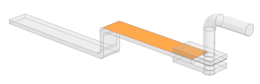
Define electrical coupling conditions
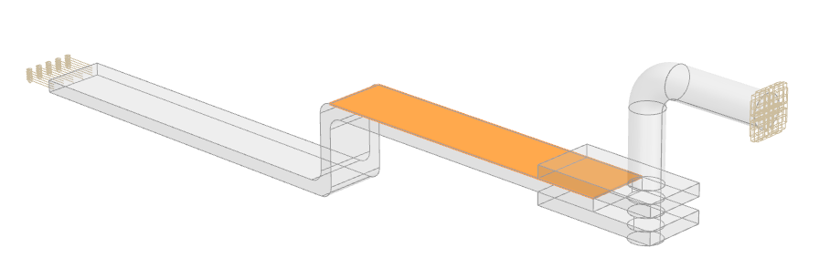
Define electrical resistance of 0.0001 Ω between two adjacent faces using the Joule Heating simulation object.
- In the Joule Heating dialog box, from the type list, select Electrical Coupling.
-
Choose Display tab→Preferences group→Emphasis list→See-Thru All.
If the Emphasis list is not available, activate the Emphasis Gallery from the Display group options.
- On the Top Border Bar, from the Type Filter list, select Polygon Face.
-
Select the primary surface of the connector as shown.
-
In the Secondary Region group, click
Select Object
 .
.
- On the Top Border Bar, from the Type Filter list, select Polygon Face.
-
Select the highlighted surface of the connector as a secondary
region.
Tip: Use Quick-Pick to select the highlighted surface. - In the Magnitude group, in the Electrical Resistance box, type 0.0001 Ω.
- Click OK.
-
In the Simulation Navigator, hide Simulation Object Container.
Explore the three existing Joule Heating simulation objects that were created for the other adjacent faces of the electrical connector.
Define thermal coupling conditions
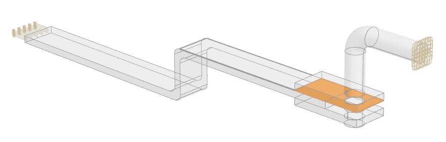
Define the thermal coupling conditions between the surfaces on which you defined the electrical coupling.
-
Choose Home tab→Loads and
Conditions group→Simulation Object
Type list→Thermal Coupling
 .
.
-
Select the primary surface of the connector as shown.
-
In the Secondary Region group, click
Select Object
.
-
Select the displayed surface of the connector.
- In the Magnitude group, from the Type list, select Heat Transfer Coefficient.
- In the Coefficient box, type 1000 W/(m2·K).
- Click OK.
- In the Simulation Navigator, hide Simulation Object Container.
- In the Simulation Navigator, explore the Convection to Environment constraint that was created for the electrical connector external surfaces, and the three others Thermal Coupling simulation objects that have been created for the other adjacent faces of the electrical connector.
Add Joule data to the result options
Activate the Joule Data output request results to display the dissipated power results in the Post Processing Navigator.
- In the Simulation Navigator, right-click the Solution 1 node and choose Edit.
-
On the Results Options page, in the
Thermal Output Requests row, click
Edit
.
- On the Thermal page, select the Joule Data check box.
- Click OK for all the dialog boxes.
Solve the model
- In the Simulation Navigator, right-click the Solution 1 node and choose Solve.
- Click OK.
- Wait for the solve to end, before proceeding.
- In the Review Results dialog box, click No.
- Close the Information window.
- In the Analysis Job Monitor dialog box, click Cancel.
Review the results
Display the temperature and power density results.
- Choose Display tab→Preferences group→Emphasis list, clear the See-Thru All check box.
- In the Simulation Navigator, expand the Solution 1 node and double-click the Results node.
- In the Post Processing Navigator, expand the Thermal node and double-click Temperature - Elemental.
-
Choose Results tab→Display
group→Edge Style drop-down
list→Feature
 .
.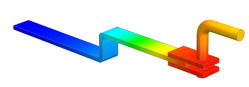
Observe the temperature distribution along the electrical connector. Notice that the highest temperature is on the faces where the thermal and electrical coupling boundary conditions are defined. - Double-click the node Power Density - Elemental.
-
Choose Results tab→Post View
group→Result
 .
.
- From the Units list, select W/m2.
-
Click OK.
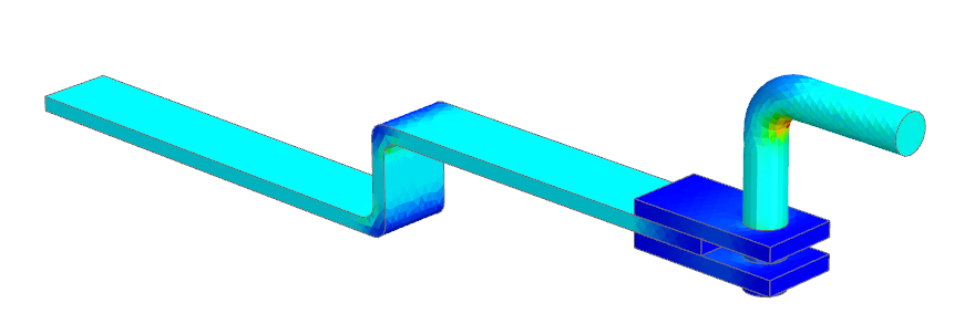
Observe the power density distribution along the electrical connector. Notice that on the faces where the thermal and electrical coupling boundary conditions are defined, the power density is minimum where the temperature of the electrical connector is maximum, which shows the Joule heating effect.