Create a heat pipe thermal device
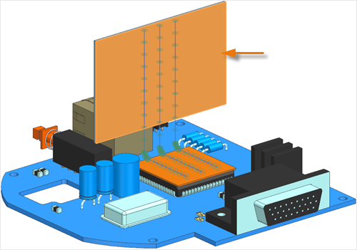
Practice to create a heat pipe thermal device to cool an electronic system in a transient simulation and post process results. The model consists of a printed circuit board (PCB) with horizontal and vertical heat sinks attached to the central processing unit (CPU). You will learn how create heat pipe thermal devices and define its thermal couplings with the heat sinks to extract the heat from the CPU.
Open the simulation file
Open the Simulation file and reset the dialog box settings.
- Choose File→Open and open heat_pipe/heat_pipe_sim.sim.
- Choose File→Preferences→User Interface and on the Dialog and Precision page, reset the dialog box memory.
-
In the Simulation Navigator, expand the Solution
1 → Simulation Objects, Constraint
Set, and Loads nodes and explore the predefined
boundary conditions applied to the solution.
- Thermal Coupling simulation objects to model the conduction between the CPU and the PCB and between the CPU and the horizontal heat sink.
- A Thermal Coupling – Radiation simulation object to model the radiation heat transfer between the horizontal heat sink and the PCB.
- Convection to Environment constraints to model the free convection to the environment from the PCB and the horizontal sink and a forced convection from the vertical heat sink.
- A Thermal Heat Load to simulate the heat generated by the CPU.
Create 1D mesh for heat pipe
Create 1D mesh on curves, which you will use to define the heat pipes.
- In the Simulation Navigator, right-click the heat_pipe_fem.fem node and choose Open in Window.
-
Choose Home tab→Mesh
group→1D Mesh
 .
.
- On the Top Border bar, from the Type Filter list, select Curve.
-
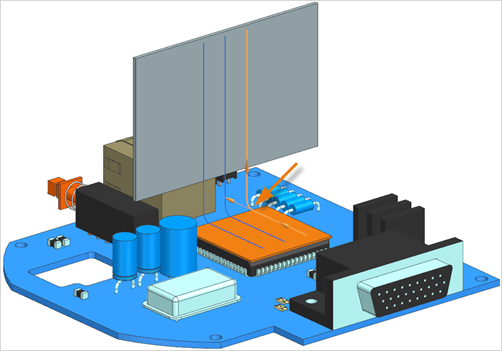
In the graphics window, select the 3 curves of the upper heat pipe as shown.
-
In the Objects to Mesh group, select the
Auto Chain Selection check box to ensure that the
directions of the selected curves are consistent.
The software uses the direction of the first selected curve to set the direction of the other curves.
-
Click Reverse Direction
 if the direction is displayed
differently.
if the direction is displayed
differently.
- In the Mesh Parameters group, in the Number of Elements box, type 10.
-
Select the Merge Nodes check box and keep the default nodes tolerance to merge coincident nodes between the endpoints of two curves.
The software merges the nodes if they are closer than the specified tolerance.
-
In the Destination Collector group, click
New Collector
 .
.
-
In the Properties group, under
Material, click Choose
material
 .
.
- From the Material List table, select Aluminum_6061.
- Click OK.
-
In the Section group, in the Fore
Section row, click Show Section
Manager
 .
.
-
In the Beam Section Manager dialog box, click
Create Section
 .
.
-
From the type list, select TUBE.
You can use any cross section, by which you get equivalent conduction along its length, and any radiation or convection on its outside surface area.
- In the DIM1 box, type 1 mm.
- In the DIM2 box, type 0.5 mm.
- Click OK in the Beam Section dialog box, Close in the Beam Section Manager dialog box, OK in the Mesh Collector dialog box, and Apply in the 1D Mesh dialog box.
- In the graphics window, select 3 curves for the middle heat pipe.
-
In the Objects to Mesh group, select the
Auto Chain Selection check box.
Notice that the other options are the same as for previous 1D mesh created.
- Click Apply.
- Repeat steps 19 and 20 to create 1D mesh on the last curves.
- Click OK.
-
In the Simulation Navigator, expand the 1D Collectors→Beam(1) nodes.
Notice that three 1D meshes are created.
- Right-click the Beam(1) node and choose Edit Display.
- From the Display Section list, select Curves.
-
Click OK.
Notice the tube display around the heat pipes in the graphics window.
Create heat pipe thermal devices
Create Thermal Devices simulation objects to define the heat pipes and specify their heat transfer coefficients.
- In the graphics window, click the (Simulation) heat_pipe_sim tabbed window to make it the work part.
-
Choose Home tab→Loads and
Conditions group→Simulation Object
Type list→Thermal Devices
 .
.
- From the type list, select Heat Pipe.
-
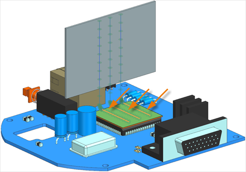
In the graphics window, select the curves of one of the heat pipes.

3 curves are selected. - In the Magnitude group, in the Coefficient box, type 2500 W/m2·°C.
- Click Apply.
- Repeat steps from 4 to 6 to define two heat pipes on the other two sets of curves.
- Click OK.
Create thermal coupling between the horizontal heat sink and heat pipe
Create a thermal coupling between the horizontal heat sink and the three heat pipes to extract the heat from the CPU.
- In the Simulation Navigator, hide Simulation Object Container to hide the created boundary condition in the graphics window.
-
Choose Home tab→Loads and
Conditions group→Simulation Object
Type list→Thermal Coupling
 .
.
-
In the graphics window, select the curves of the three heat pipes parallel to the
horizontal heat sink as the primary region.
- Expand the Secondary Region group.
- In the Secondary Region group, click Select Object.
-
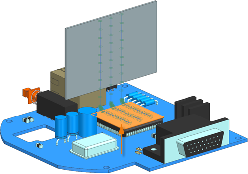
In the graphics window, select the horizontal heat sink source top surface.
- In the Magnitude group, from the Type list, make sure that Total Conductance is selected and, in the Conductance box, type 1000 W/°C.
- Click Apply.
Create thermal coupling between the vertical heat sink and heat pipe
Create a thermal coupling between the vertical heat sink and the three heat pipes.
-
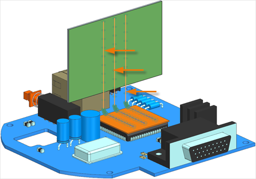
In the graphics window, select the shown curves of the three heat pipes parallel to
the vertical heat sink as the primary region.
- In the Secondary Region group, click Select Object.
-
In the graphics window, select the vertical heat sink top surface.
- In the Magnitude group, in the Conductance box, type 1000 W/°C.
- Click OK.
Define advance parameters to output data for the heat pipes
Use an advanced parameter to create post processing output data for the heat pipes.
-
Choose Home tab→Loads and
Conditions group→Simulation Object
Type list→Advanced Controls
 .
.
- Make sure that the Advanced Parameter type is selected.
- In the Parameter Definition group, click Catalog.
- Expand the Thermal→Thermal Output nodes and select the DISPLAY BC SUMMARY TABLES node to output tables summarizing the properties of heat pipe boundary conditions in the heat_pipe_sim-Solution_1.bcdata file.
- Click OK and Apply.
-
In the Parameter Definition group, click
Catalog
 .
.
- Under the Thermal→Thermal Output node, select the PLOT BC SUMMARY node to generate an HTML file containing the properties of the heat pipe boundary conditions in the heat_pipe_sim-Solution_1_data.html file.
- Click OK twice.
Solve the model
- In the Simulation Navigator, right-click the Solution 1 node and choose Solve.
- Click OK.
-
In the Simulation Navigator, right-click the Solution 1 node and choose Browse.
Notice that as the solution progresses the heat_pipe_sim-Solution_1.bcdata and heat_pipe_sim-Solution_1_data.html files become available. You requested these files in the Advanced Controls simulation objects.
- Open the heat_pipe_sim-Solution_1.bcdata file in a browser.
- Under the graph, from the Property Type list, select the Area Cond.
- From the Select Heat Pipes list, select the Thermal Devices(1).
- From the Select Second Heat Pipes list, select the Thermal Devices(2).
- Hover on the graph and explore the results. You see the condenser effective area and the evaporator effective area for the two heat pipes evolve over time.
-
Open the heat_pipe_sim-Solution_1_data.html file using a text editor.
Explore the file. For each heat pipe, you see:
- TIME is the solution time steps.
- Tvap is the vapor nodal temperature.
- CHR-EVAP is the total heat load for the evaporator elements.
- CHR-COND is the total heat load for the condenser elements.
- AREA-EVAP is the evaporator effective area.
- AREA-COND is the condenser effective area.
This tabular data is the same information that is displayed in the browser.
- In Simcenter 3D, wait for the solve to end, before proceeding.
-
In the Review Results dialog box, click No.
After some time, the Solution Monitor closes automatically without your input.
- In the Analysis Job Monitor dialog box, click Cancel.
- Close the Information window.
Display results
- In the Simulation Navigator, expand the Solution 1 node and double-click the Results node.
- In the Post Processing Navigator, expand the Thermal-Flow→Increment 101, 100.00s nodes and double-click the Temperature - Elemental node.
- Expand the Post View 1→Mesh Collectors→heat_pipe_fem.fem nodes.
-
Hide Mesh Collectors and show 1D
Elements.
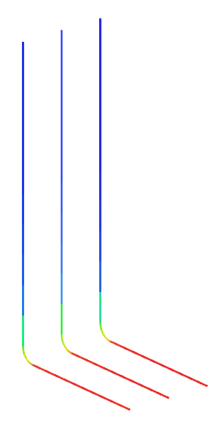
Heat pipes extract the heat dissipated by the electronic component from its horizontal bottom part and carries the heat to its vertical cold ends.