Model a Peltier cooler
Practice modeling the Peltier cooler of an electronic component. You will compare the temperature distribution with and without a Peltier cooler.
Open the model Simulation file
Open the Simulation file and reset the dialog box settings.
- Choose File→Open and open peltier_cooler/mc_02_sim1.sim.
- Choose File→Preferences→User Interface and on the Dialog and Precision page, reset the dialog box memory.
- Click OK.
View the temperature distribution on the component without the Peltier cooler
Observe the temperature of the chip without a Peltier cooler from the results of the existing Thermal solution.
- In the Simulation Navigator, expand the Solution 1→Results nodes and double-click the Thermal node.
-
Expand the Thermal node and double-click the
Temperature - Elemental node.
Create a new thermal solution
Create a new solution that will contain the results of the thermal simulation with the Peltier cooler.
-
Choose Results tab→Return to
Home
 .
.
- In the Simulation Navigator, right-click Solution 1 and choose Clone.
-
Right-click the Copy of Solution 1 node, choose Rename, and type Solution 2.
Notice that the new Solution 2 contains the same boundary conditions as Solution 1.
Add the Peltier cooler components to the model
Add and mesh two new components to define a Peltier cooler in the next step.
- In the Simulation Navigator, right-click the mc_02_fem_i_fem1.fem node, and choose Make Work Part.
- Expand the mc_02_fem_i_fem1.fem node and right-click the mc_02_fem_i.prt node and choose Load.
- Right-click the mc_02_fem1.fem node and choose Edit.
- In the CAD Part group, select the Edit Bodies to Use check box to select the bodies to add to the FEM file.
-
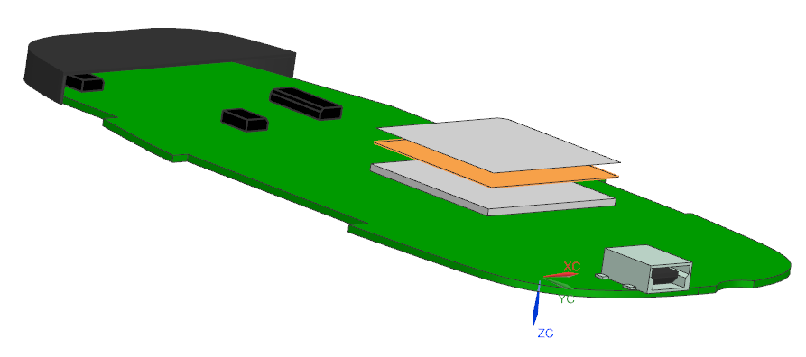
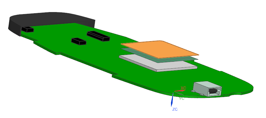
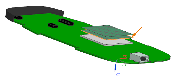
In the Idealized Part window, select the two
surfaces above the CPU.
14 bodies are selected. - Click OK.
-
Choose Home tab→Mesh
group→2D Mesh
 .
.
-
Select the highlighted surface.
- In the Element Properties group, from the Type list, select Linear Quadrilateral - CQUAD4.
- In the Mesh Parameters group, in the Element Size box, type 3 mm.
- In the Destination Collector group, clear the Automatic Creation check box.
- In the Mesh Collector list, select peltier.
- Click Apply.
-
Select the highlighted surface.
- Click OK.
Define the Peltier cooler
Use the two new components to define a Peltier Cooler simulation object.
- In the Simulation File View subpanel, right-click the mc_02_sim1.sim node and choose Make Work Part.
-
Choose Home tab→Loads and
Conditions group→Simulation Object
Type list→Thermal Devices
 .
.
- Make sure that the type is set to Peltier Cooler.
-
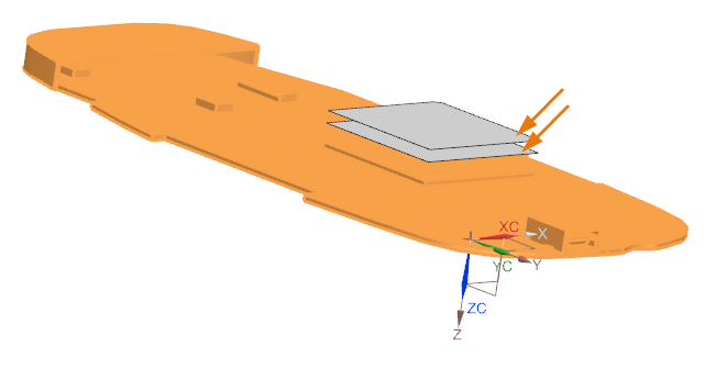
Select the shown plate as the cold plate region.
-
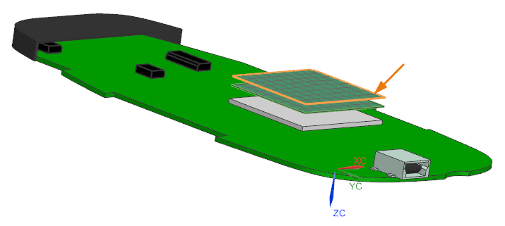
In the Hot Plate Region group, click
Select Object
 .
.
-
Select the shown plate, as a hot plate region.
-
In the Parameters group, set the following:
- Seebeck Coefficient = 0.000207 V/°C
- Electrical Resistivity = 0.009998 Ω·mm
- Thermal Conductivity = 0.0015 W/(mm·°C)
- Number of Couples = 127
- Geometric Factor = 0.519 mm
- Electrical Boundary Condition = Current
- Current = 0.1 A
- Click OK.
Apply and define the thermal boundary conditions
Create a thermal coupling between the cold plate of the Peltier cooler and the CPU top surface, and you will modify the convection to environment constraint of the CPU by applying it to the hot plate of the Peltier cooler.
- In the Simulation Navigator, under the mc_02_fem1.fem node, hide 2D Collectors.
- Hide Simulation Object Container.
-
Choose Home tab→Loads and
Conditions group→Simulation Object
Type list→Thermal Coupling
 .
.
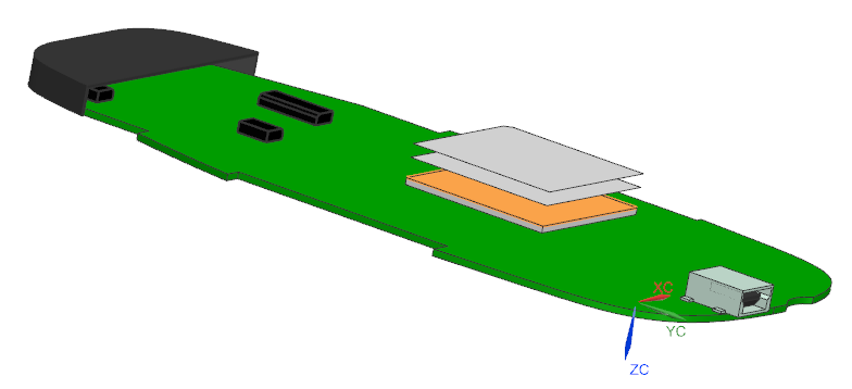
-
Select the highlighted top surface of the CPU.
-
In the Secondary Region group, click
Select Object
.
-
Select the highlighted cold plate of the Peltier cooler.
- In the Magnitude group, from the Type list, select Heat Transfer Coefficient.
- In the Coefficient box, type 200 W/(mm2·C).
- Click OK.
- Modify the CPU convection to environment constraint by applying it to the hot plate of the Peltier cooler.
- In the Simulation Navigator, hide Simulation Object Container.
- Expand the Constraint Container node, right-click the CPU top convection to environment constraint and choose Edit.
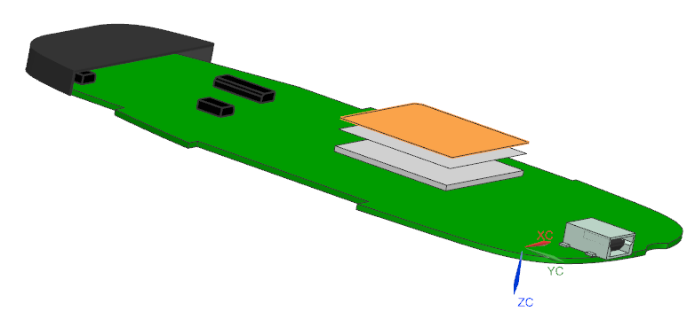
- Press shift on your keyboard and click the top surface of the CPU to deselect it. In the Region group, the number of Select Object must now be zero.
- Select the displayed hot plate of the Peltier cooler.
- Click OK.
Apply and define the thermal boundary conditions
Create a thermal coupling between the cold plate of the Peltier cooler and the CPU top surface, and you will modify the convection to environment constraint of the CPU by applying it to the hot plate of the Peltier cooler.
- In the Simulation Navigator, under the mc_02_fem1.fem node, hide 2D Collectors.
- Hide Simulation Object Container.
-
Choose Home tab→Loads and
Conditions group→Simulation Object
Type list→Thermal Coupling
.
-
Select the highlighted top surface of the CPU.
-
In the Secondary Region group, click
Select Object
.
-
Select the highlighted cold plate of the Peltier cooler.
- In the Magnitude group, from the Type list, select Heat Transfer Coefficient.
- In the Coefficient box, type 200 W/(mm2·C).
- Click OK.
Modify the CPU convection to environment constraint
Modify the CPU convection to environment constraint by applying it to the hot plate of the Peltier cooler.
- In the Simulation Navigator, hide Simulation Object Container.
- Expand the Constraint Container node, right-click the CPU top convection to environment constraint and choose Edit.
-
Press shift on your keyboard and click the top surface of the CPU to
deselect it.
In the Region group, the number of Select Object must now be zero.
-
Select the displayed hot plate of the Peltier cooler.
- Click OK.
Solve the solution
- Right-click the Solution 2 node and choose Solve.
- Click OK.
- Wait for the solve to end, before proceeding.
- In the Review Results dialog box, click No.
- Close the Information window.
- In the Analysis Job Monitor dialog box, click Cancel.
Review the results
Display and compare the temperature distribution on the CPU with and without the Peltier cooler.
-
Choose Results tab→View
Layout group→Side by Side
 .
You have a two-view layout to compare the results with and without the Peltier cooler.
.
You have a two-view layout to compare the results with and without the Peltier cooler. -
Choose Results tab→View
Layout group→View Synchronize
 .
.
-
Select the two viewports in the graphics window, and in the
Viewport Settings dialog box, choose OK
 .
You have synchronized the view operations for the two viewports of the graphics window.
.
You have synchronized the view operations for the two viewports of the graphics window. - Right-click in the graphics window, and choose Fit.
- In the Simulation Navigator, under Solution 2, double-click the Results node.
- In the Post Processing Navigator, expand the Solution 2→Thermal nodes, and double-click Temperature – Elemental.
- Select the left viewport in the graphics window.
- Under the Contour Plots node, expand the Post View 2→Mesh Collector→mc_02_fem1.fem→2D Elements nodes, and hide peltier to hide the Peltier cooler from the results.
- In the Post Processing Navigator, under the Solution 1→Thermal nodes, double-click Temperature – Elemental.
- Select the right viewport in the graphics window.
-
Right-click in the graphics window, and choose View→Orient View→Bottom
 .
.
- Press Ctrl, and select the right and left viewports in the graphics window.
-
Choose Results tab→Post View
group→Edit Post View
 .
.
- In the Legend tab, in the Color Bar group, from the Legend Extremes list, select Specified.
-
Click OK.
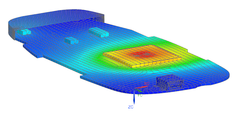
You set the same maximum and minimum values for the two temperature scales from the results obtained without the Peltier cooler.
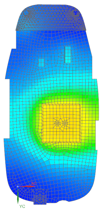
Figure 1. Temperature distribution with the Peltier cooler 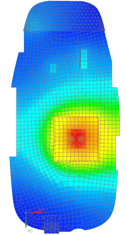
Figure 2. Temperature distribution without the Peltier cooler You can observe that with the Peltier cooler, the temperature of the CPU is colder, and the temperature distribution is uniform on the top surface for the CPU.