Import a PCA model from ECAD
Practice to import a PCA model from ECAD using PCB Exchange.
Set the environment variable
Set an environment variable to use the basic PCB Exchange application.
- Click on the Start button or press the Windows key on your keyboard.
- In the search bar, type Environment Variables and select Edit environment variables for your account from the search results.
- In the Environment Variables dialog box, under User Variables for student, click New.
- In the Variable name box, type UGII_PCBX_VARIANT.
- In the Variable value box, type Modeler.
- Restart Simcenter 3D.
Create a new model and start PCB Exchange
Create a new model, start the PCB Exchange application, and reset the dialog box settings.
- Choose File→New and create a new part file in the asm_pcb folder using the Blank template.
-
Choose Application tab→Design
group→More list→PCB
Exchange
 .
.
- Choose File→Preferences→User Interface and on the Dialog and Precision page, reset the dialog box memory.
Set general PCB Exchange preferences
Get familiar with the options available in the PCB Exchange Preferences dialog box. CAD files contain the component locations, layouts, and heights. When importing an ECAD file, you can choose to import the components as parts in the PC assembly or features in the board file. In this example, you will import them as separate parts.
-
Choose Home tab→Data Exchange
group→Preferences
 .
.
-
On the General tab, in the Read/Write Directory box, click Browse and select the asm_pcb folder.
The software writes the log and temporary files in this directory.
-
Clear the Automatically Save All Created Parts check box to avoid populating file databases with dummy components.
PCB Exchange creates and displays the parts but saves the files only when you choose to save them.
- On the PCA tab, verify that the Import Component Workflow list is set to Load and Create Components.
-
Verify that the Group Entity Components by list is set to None.
Keep the PCB Exchange Preferences dialog box opened.
Set the board, component, hole, and area properties
Modify the settings for the board, holes, and components, such as the board color and thickness, the default hole diameter, and the component part creation folder, which you set to the root folder where you are working.
- On the Board tab, in the General Settings group, select the Color swatch, and then select the Emerald (ID 108) color in the color palette.
- Click OK to close the Object Color dialog box.
- In the Default Thickness box, type 2.5 mm.
- On the Holes tab, in the Default Diameter box, type 0.15 mm.
- On the Components tab, in the New Component Directory group, from the New Component Source list, select NX Part Directory.
-
On the Areas tab, observe the properties for the restriction areas.
Restriction areas are a means of exchanging design intent between mechanical and electrical designers. For example, there may be regions of a board where no electrical component may reside as it would interfere with the chassis surrounding the board. The mechanical designer would indicate this using a keep-out area restriction.
- Click OK.
Import an ECAD model
Import an ECAD model in an empty part file to which the board is imported as the root assembly.
-
Choose Home tab→Data Exchange
group→Import ECAD Model
 .
.
- In the ECAD Model group, in the Board File box, click Browse and select the asm_pcb\pcbdemo.brd file.
- In the Import Options group, verify that the Only Use Existing Components check box is cleared.
- Click OK.
- Close the Information window.
-
On the Resource bar, click the Assembly Navigator
 .
.
-
In the Assembly Navigator, select one part check
boxes to display all the component parts in the graphics window.
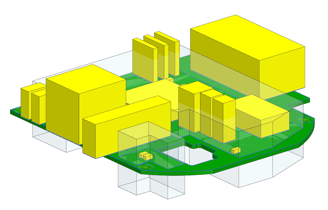
Explore the imported model
Familiarize yourself with the imported model using the PCB Design Navigator and learn how to modify it.
-
In the Assembly Navigator
, observe how the assembly components have a
part name corresponding to the electrical package name.
-
On the Resource bar, click the PCB Design Navigator
 .
Notice that the components are listed by their reference designators in the Component panel.
.
Notice that the components are listed by their reference designators in the Component panel. - In the Board panel, right-click the board and choose Edit.
- In the Board Attributes group, in the Revision box, type 1.
-
Click OK.
Notice that the board version changed in the Board panel.
- In the Component panel, right-click Z2 and choose Edit.
- In the Components Attributes group, in the Reference Designator box, type Z37.
- Click OK.
Validate the PCA
-
Choose Home tab→Data Exchange
group→Validate PCA
 .
The information window displays that the assembly is valid.
.
The information window displays that the assembly is valid. - Close the Information window.
-
On the Resource bar, in the Web Browser
 tab, explore the PC
Assembly Information.
tab, explore the PC
Assembly Information.
Import the detailed assembly
Create a new assembly file, in which you will import the same ECAD model you imported before, this time specifying a parts folder to locate the detailed components. You will also filter out mounting holes. First, you need to close all imported component parts, because the software does not support multiple loaded parts with the same name.
- Close all parts without saving.
- Choose File→New and create a new part file in the asm_pcb folder using the Blank template.
-
Choose Application tab→Design
group→More list→PCB
Exchange
.
-
Choose File→Assembly Load
Options
 .
.
- In the Part Versions group, from the Load list, select From Search Folders.
- In the Add Folder to Search box, click Browse and select the asm_pcb\library folder.
- Click OK to close both dialog boxes.
-
Choose Home tab→Data Exchange
group→Import ECAD Model
.
- In the ECAD Model group, in the Board File box, notice that the pcbdemo.brd file is still selected.
-
In the Import Options group, select the
Use Entity Filter check box and click
Filter List
 .
.
- On the Pre-Defined Filters tab, in the Holes group, select the Remove Mounting Holes check box.
- Click OK to close both dialog boxes.
- Close the Information window.
-
On the Resource bar, click the Assembly Navigator
.
-
In the Assembly Navigator, select one part check
boxes to display all component parts in the graphics window.
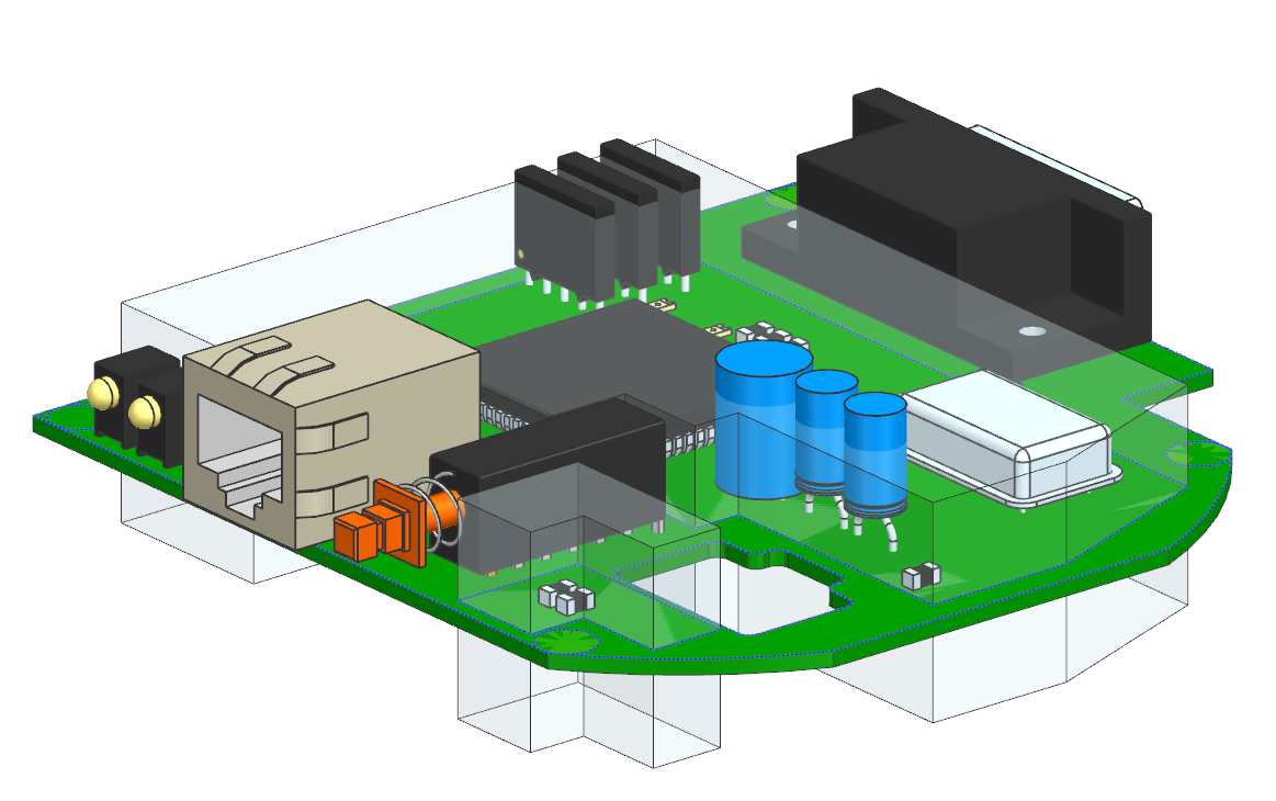
This time, PCB Exchange found the existing part files in the library and used them to create the assembly. The mounting holes are not present in the board.
Validate the detailed PCA
-
Choose Home tab→Data Exchange
group→Validate PCA
.
The information window displays that the assembly is valid.
- Close the Information window.
-
On the Resource bar, in the Web Browser
, explore the PC
Assembly Information.
Notice that there are 22 warnings and some components are shown in red in the report.
-
In the Web Browser, under PC Assembly
Information, click on the Assembly is
valid link to display the warnings.
Notice that some components are positioned inside the board.