Define thermal boundary conditions
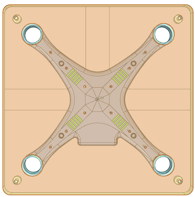
Practice defining thermal boundary conditions on a drone mold. You will specify thermal simulation objects, initial conditions, and constraints.
Open the Simulation file
Open the model Simulation file and reset the dialog box settings.
- Choose File→Open and open mold/drone_mold_sim.sim.
-
Choose
File→Preferences→User
Interface, on the Dialog and
Precision page, click Reset Dialog
Memory
 .
.
- Click OK.
Define report requests
Set up temperature report requests over the drone region.
-
Choose Home tab→Loads and
Conditions group→Simulation Object
Type→Report
 .
.
- From the Type list, ensure Per Region is selected
- In the Region group, select the Group Reference check box and choose mold::drone_mold_fem from the list.
- In the Thermal Data group, select the Temperature check box.
-
Click OK.
A temperature report will be generated during solution.
-
In the Simulation Navigator, under
Simulation Object Container node, click
 next to the
Report(1) node to hide it.
next to the
Report(1) node to hide it.
Define initial conditions
Create initial temperature conditions for the drone and mold.
-
Choose Home tab→Loads and
Conditions group→Constraint
Type→Initial Conditions
 .
.
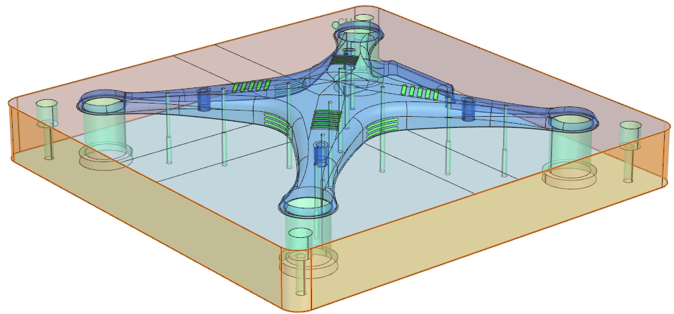
- In the Region group, select the Group Reference check box and select drone::drone_mold_fem from the list.
- In the Initial Temperature group, set Temperature to 210 °C.
- Click Apply.
- In the Region group, select the Group Reference check box and select mold::drone_mold_fem from the list.
- Set Temperature to 90 °C.
- Click OK.
- In the Simulation Navigator, hide the Constraints Container node.
Define convection to environment constraints
Create convection constraints between mold surfaces and environment.
-
Choose Home tab→Loads and
Conditions group→Constraint
Type→Convection to Environment
 .
.
- From the Type list, select Free Convection to Environment .
-
Select the polygon face on the mold bottom.
- In the Parameters group, from the Correlation list, select Horizontal Plate.
- Click Apply.
- In the Simulation Navigator, hide the Constraints Container node.
-
Select 8 polygon faces on the mold perimeter.
- In the Parameters group, from the Correlation list, select Inclined Plate.
-
Click OK.
Thermal boundary conditions are now defined on the model.
Add the boundary condition
Add all defined boundary conditions to the active solution.
- In the Simulation Navigator, double-click Solution 1 to make it active.
- In the Simulation Navigator, expand the Simulation Object Container and Constraint Container nodes.
- Click Report(1), press and hold Ctrl, and select Initial Conditions(1), Initial Conditions(2), Convection to Environment(1), and Convection to Environment(2) nodes.
-
Right-click the selected nodes and choose Add to active solution
or step.
Boundary conditions are now added to the model.
Solve the thermal model
Solve the model and monitor solution status.
- In the Simulation Navigator, right-click the Solution 1 and choose Solve.
- Click OK.
- Wait for the simulation to complete; status shows Complete in Analysis Job Monitor.
- In the Review Results dialog box, click No.
- Close the Information window.
- Click Cancel in the Analysis Job Monitor dialog box.
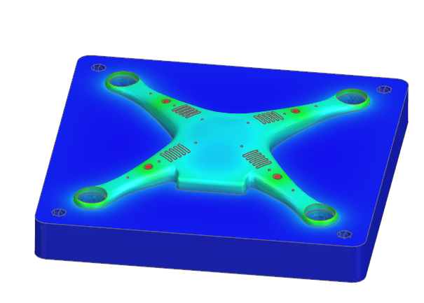
Display the thermal analysis results
Load and review temperature results and summary reports.
- In the Post Processing Navigator, under Solution 1, right-click Thermal node and choose Load.
- Expand Thermal → Increment 11, 10.00s nodes.
-
Double-click Temperature - Nodal.
- Browse to the solution directory and open drone_mold_sim-Solution_1.GroupReport.html to view the temperature summary table.