Create a 1D duct network in a mold
Practice creating immersed ducts in a mold. You will create a 1D collector and display the ducts in the model.
Open the model Simulation file
Open the model Simulation file and reset the dialog box settings. You can also continue working on the Simulation file from the previous lab.
- Choose File→Open and open mold_duct/drone_mold_sim.sim.
- Choose File→Preferences→User Interface and on the Dialog and Precision page, reset the dialog box memory.
Create ducts in the mold
- In the Simulation Navigator, double-click the drone_mold_fem.fem node and expand it.
- Hide Polygon Geometry.
-
Choose Home tab→Mesh
group→1D Mesh
 .
.
-
Select the displayed line.
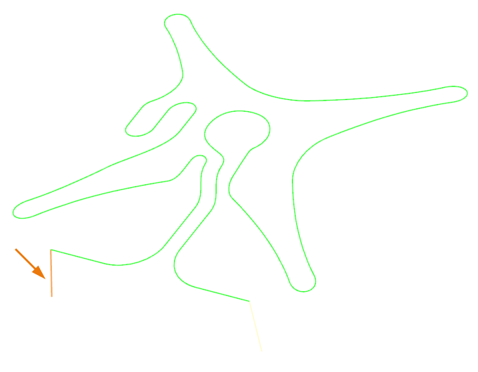
- In the Element Properties group, from the Type list, select DUCT.
- In the Mesh Parameters group, in the Number of Elements box, type 20.
- Select the Merge Nodes check box.
-
In the Destination Collector group, click
New Collector
 .
.
- In the Properties group, in the Name box, type water_duct.
- From the Fluid Material list, select Water.
-
In the Fore Section row, click Show
Section Manager
 .
.
-
Click Create Section
 .
.
- In the Properties group, in the DIM1 box, type 2.5 mm.
- Click OK, Close, OK, and Apply.
-
In the graphics window, select the displayed line.
- Click Apply.
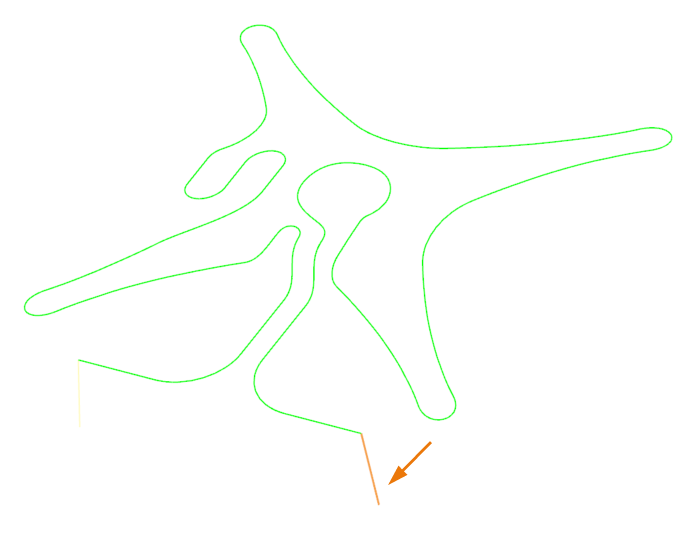
-
In the graphics window, select the displayed curve.
-
Click Reverse Direction
 if required.
- In the Mesh Parameters group, in the Number of Elements box, type 500.
- Click OK.
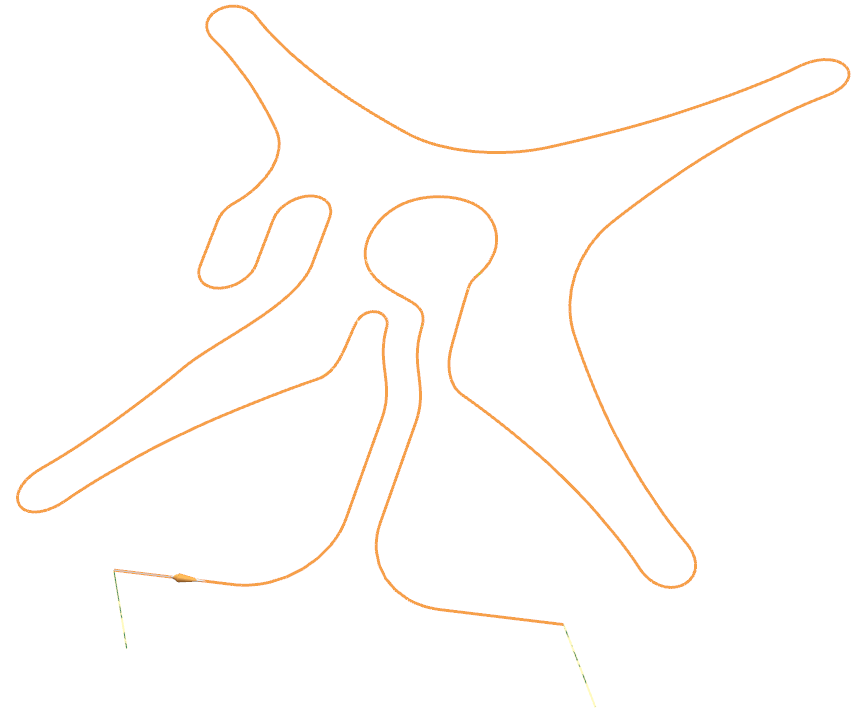
Display the ducts
- In the Simulation Navigator, expand the 1D Collectors node.
- Right-click the water_duct node and choose Edit Display.
- Click the color swatch.
- In the Find box, type Black, and select the color.
- Click OK.
- From the Display Section list, select Solid.
-
Click OK.
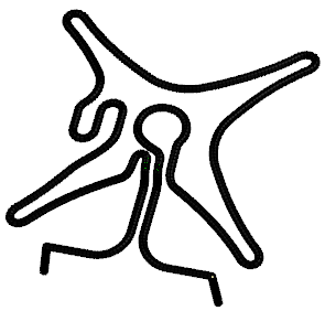
- In the Simulation Navigator, show Polygon Geometry.
-
In the Simulation File View, double-click the
drone_mold_sim.
The ducts are now created. You will define the duct boundary conditions, and solve the model in the next lab.