Simulation process in Simcenter 3D Pre/Post
Practice setting up and solving a model using Simcenter 3D Pre/Post.
Open the model Simulation file
Open the model Simulation file and reset the dialog box settings.
- Choose File→Open and open brake\brake_assembly_x_t_sim1.sim.
-
Choose File→Preferences→User Interface and on the Dialog and Precision page, reset the dialog box memory.
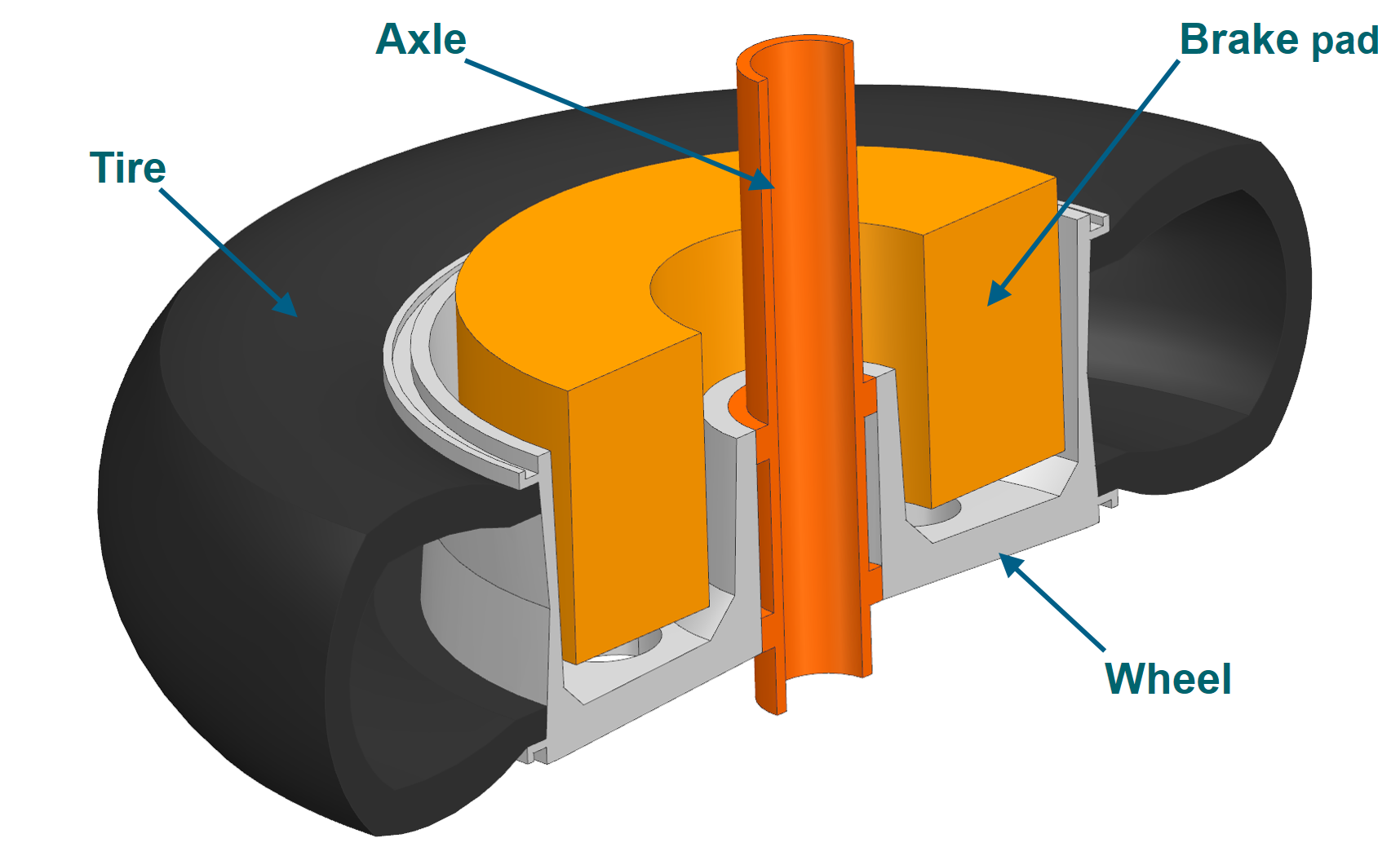
The brake assembly includes four components.
Mesh the brake pad
With the FEM file as the work part, create a 3D mesh on the brake pad part.
- In the Simulation Navigator, right-click the brake_assembly_x_t_fem1.fem node and choose Make Work Part.
- Explore the meshes that have been created for the axle, tire, and the wheel.
-
Choose Home tab→Mesh group→3D Tetrahedral
 .
.
- In the graphics window, select the brake pad.
- In the Mesh Parameters group, in the Element Size box, type 20 mm.
-
In the Destination Collector group, click New Collector
 to create a destination collector for 3D mesh.
- In the Properties group, from the Material list, select the Ceramic Compound.
- In the Name box, type brake_pad_collector.
- Click OK for all dialog boxes.
-
In the Simulation Navigator, under the brake_assembly_x_t_fem1.fem node, click
 to hide 3D Collectors.
Create a solution
- In the Simulation Navigator, right-click brake_assembly_x_t_sim1.sim and choose Make Work Part.
-
Choose Home tab→Solution group→Solution
 .
.
- From the Solver list, select the appropriate solver. For this example, the Simcenter 3D Thermal/Flow is selected.
- Click Create Solution.
- In the Solution group, in the Name box, type Steady.
- Click OK.
Apply boundary conditions
-
In the Simulation Navigator, explore the boundary conditions that have been created for this tutorial:
- Convection to environment constraints for wheel, brake, and tire.
- Thermal coupling between brake pad and the wheel.
Note that the wheel, tire, and axle are connected using mesh mating.
- Under the Constraint Container node, select the three constraints and drag to the Constraint Set node, under Steady to activate them.
- Under the Simulation Object Container node, select the Brake_wheel_TC simulation object and drag it into the Simulation Objects node under Steady to activate it.
-
Choose Home tab → Loads and Conditions group→Load Type→Thermal Loads.

- In the Name group, type 2000 W.
-
In the graphics window, select the shown face.
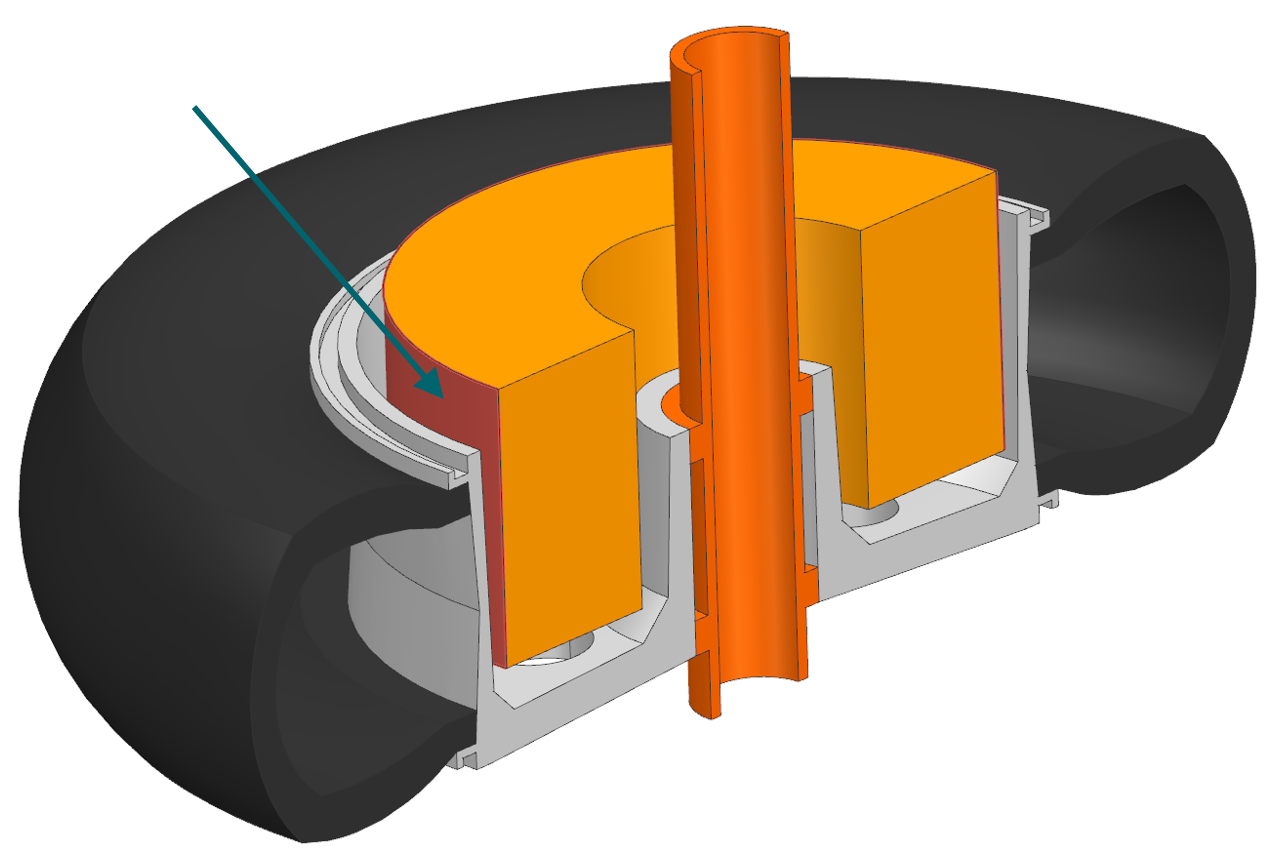
- In the Magnitude group, enter 2000 W in the Heat Load box.
- Click OK.
Solve the model
- Right-click the Steady node in Simulation Navigator and choose Solve.
-
Click OK.
The solution takes about 2 minutes. The Analysis Job Monitor should show Completed Successfully.
- In the Review Results dialog, click No.
- Close the Information window.
- Click Cancel in the Analysis Job Monitor dialog box.
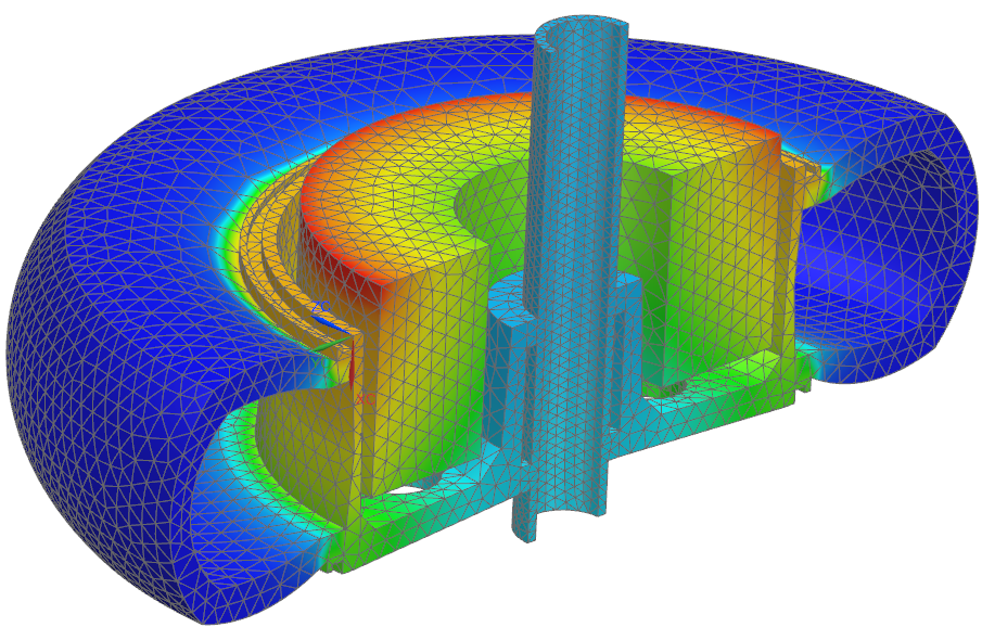
Display results
- In the Post Processing Navigator, double-click the Thermal node to load results.
- Expand the Thermal node to see all result types.
-
Double-click Temperature – Nodal to display nodal temperature results.