Model the robot arm motion using articulation
Practice defining articulation in a robot arm model. You will define the robot joints and articulation to model the robot arm motion.
Open the model Simulation file
Open the Simulation file and reset the dialog box settings.
- Choose File→Open and open robot_arm\Robot_assembly_assyfem1_sim1.sim.
- Choose File→Preferences→User Interface and on the Dialog and Precision page, reset the dialog box memory.
-
Click OK.
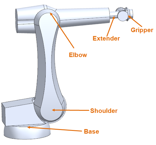
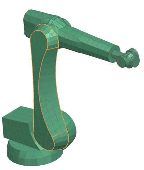
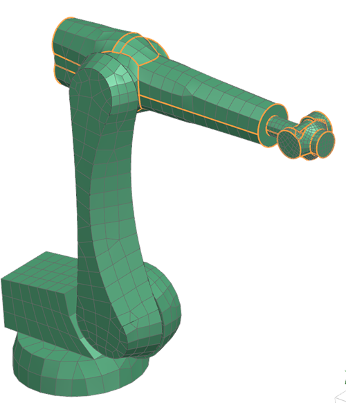
The robot arm is designed to help maintenance crew with repairs and construction. It performs limited tasks, such as holding components in a place. It is designed to move slowly to reduce the risk to the crew, during the testing phase. You will model this robot arm motion using articulation. The robot arm model includes five components: base, shoulder, elbow, extender and gripper. The model is meshed and all the material and properties are defined.
Define shoulder joint
Define a robot shoulder joint, which controls the joint movement during an analysis.
-
Choose Home tab→Properties
group→Modeling Objects
 .
.
- In the Create group, from the Type list, select Joint.
- Click Create.
- In the Name box, type Shoulder Joint.
- In the Magnitude group, from the Rotation Rate Type list, select Field.
-
From the Specify Field list, choose Table
Constructor
 .
.
- On the Name page, type Shoulder rotation.
-
On the Definition page, click Import from
Text File
 .
.
-
Click Browse
 .
.
- Select the sinusoid_arm_1.csv file located in the simulation directory.
- Click OK three times.
-
In the Magnitude group, click
Plot(XY)
 .
.
-
Click Create a New Window to Plot
 .
.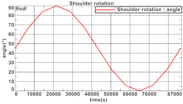
Notice that the shoulder starts at a 45° angle and rotates through its physical range over the course of one day. - Close the Graphics Window.
-
In the Orientation group, from the
Specify Vector list, select the -ZC
axis
 .
.
- Click Specify Point.
-
From the Type list, select
Arc/Ellipse/Sphere Center
 .
.
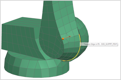
-
In the graphics window, select the displayed polygon edge as the point of
rotation.
- Click OK.
Define elbow joint
Repeat the same procedure from step 3 through to 14 used to define the shoulder joint, to create the elbow joint.
| Item | Setting |
|---|---|
| Name | Elbow Joint |
| Table Fields Name | Elbow rotation |
| Import from Text File | sinusoid_arm_2.csv |
| Specify Vector | -ZC axis |
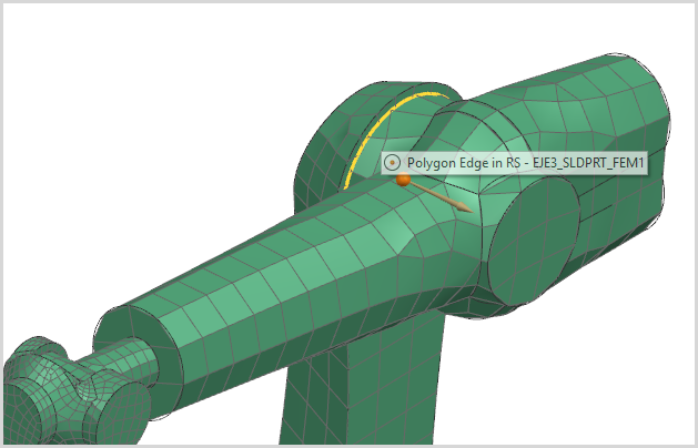
-
Click Specify Point, and select the arc center of
the polygon edge as shown.
- In the Parent Joint group, from the Select Joint list, select Shoulder Joint. The position of the elbow joint is dependent on the rotation of the shoulder joint.
- Click OK.
- Click Close.
Define the shoulder and elbow articulation
Define the robot shoulder and elbow articulation.
-
Choose Home tab→Loads and
Conditions group→Simulation Object
Type list→Solid Motion Effects
 .
.
- In the Name box, type Shoulder Articulation.
-
In the Region group, click Select
Object
 .
.
- On the scene toolbar, from the Method list, choose Related Faces.
-
In the graphics window, select the following 6 polygon faces.
- In the Joint Selection group, from the Joint list, select Shoulder Joint.
- Click Apply.
-
Repeat the same procedure from step 2 to 7, to create the elbow articulation with the settings in the following table.
Item Setting Name Elbow Articulation Joint Selection Elbow Joint -
In the graphics window, select the elbow part, the extender, and the
gripper 38 faces.
- Click OK.
Define articulation parameters
Define constant time intervals method to compute time steps for the articulation modeling of 1 day period.
- In the Simulation Navigator, right-click Solution 1 node, and choose Edit.
- In the Transient Setup page, in the Articulation Parameters group, in the Start Time box, type 0 s.
- In the End Time box, type 86400 s.
- In the Calculation Interval box, type 7200 s.
- Click OK.
-
Choose File tab→Save
 to save the modification in the simulation
file.
to save the modification in the simulation
file.
Solve the model
- Right-click the Solution 1 node and choose Solve.
- Click OK.
- Wait for the solve to end, before proceeding.
- In the Review Results dialog box, click No.
- Close the Information window.
- In the Analysis Job Monitor dialog box, click Cancel.
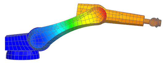
View the articulation motion results
- In the Simulation Navigator, expand the Solution 1 node and double-click the Results node.
-
In the Post Processing Navigator, expand the
Thermal → Increment 15,
7200s nodes and double-click the Articulation
Displacement - Nodal node.
Animate the articulation motion results
-
Choose Results tab→Animation
group→Animate
 .
.
- From the Animate list, select Iterations.
- In the Synchronized frame delay (mS), type 400.
-
Click Play
 .
.
-
Click Stop
 .
.
- Click Close.