Introducing 2D-3D hybrid mapping
This topic explains how to transfer thermal results between 2D axisymmetric and 3D models using hybrid mapping techniques, alignment tools, and mapping constraints for detailed thermal and structural analyses.
This lesson may include hands-on exercises. Review the Discussion section for background information or click the button to proceed to the practical section.
Discussion
2D-3D hybrid mapping allows you to map thermal results from a source model to a target model with different mesh types. Both the source model and the target model can have different element configurations such as:
- 2D axisymmetric elements
- 3D elements
- Combination of 2D axisymmetric and 3D elements
Mapped results are written to a [simulation_name]-[solution_name].bun file. A [simulation_name]-[solution_name].map file is used by the solution to retrieve the regions where mapping is defined in the source and target models.
| Thermal solution | Structural solution |
 |
 |
| Source | Target |
- Mapping from 3D source to 3D target and 2D source to 2D target elements
- The software uses the proximity method, when 3D source elements is mapped
to 3D target elements, and 2D source elements to 2D target elements.
The target node is inside the source element The target node is outside the source element 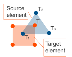
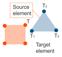
The temperature is interpolated using the nodal temperatures of all nodes of the associated source element, including midside nodes for parabolic elements. The temperature is extrapolated using the nodal temperatures of all nodes of the associated source element, including midside nodes for parabolic elements. - Mapping 2D axisymmetric source elements to 3D target elements
- The software rotates each target node around the source axisymmetric axis so
that the rotated position lies in the source axisymmetric plane. Then, it
uses the proximity method to interpolate or extrapolate the nodal
temperatures of the containing or closest source element to the rotated
target position.
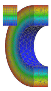
Figure 1. 2D axisymmetric to 3D elements temperature mapping - Mapping 3D source elements to 2D axisymmetric target elements
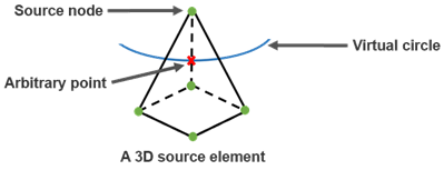
- The software uses the circumferential averaging method, where it:
- Rotates the target node around the symmetry axis to create a virtual circle.
- Interpolates the thermal results of the nodes of each source element to an arbitrary point of the intersection arc.
- Associates the average of the interpolated values to the target node.
To conduct a 2D-3D mapping solution, you must have:
- The target solution with Mapping analysis type.
- The bun file generated from the source solution that contains the mapped results.
- The mapping file that is used by the target solution to retrieve the regions where mapping is defined in the source model.
- Aligning target and source models automatically
- To automatically align the source model to the target model with different
2D-3D hybrid meshes, the solver uses one of the following options:
- The 2D Solid Option of both models.
- The cyclic symmetry cylindrical coordinate system in the source model and the 2D Solid Option of the target model.
The thermal solver ignores any rotation specified in Source Model Mapping.
- Aligning target and source models manually
- To manually align the source model to the target model, you can use the
Source Model Mapping command, which allows you to
align the target model to any mesh selected as an XML file.
The alignment tools allow users to define the rotation, translation and scaling operations to align the source model onto the target model.
The software aligns source-model coordinates with target-model coordinates, altering the source-model position while keeping the target model unchanged.
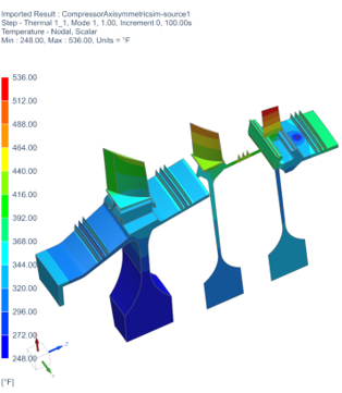
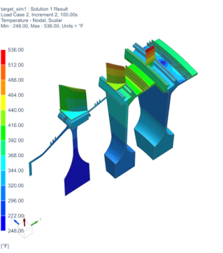
Figure 2. Source (in blue) and target models with noncongruent geometries after alignment - Source and target model geometry
- In this example, the axisymmetric mapping analysis, contains source and
target models with mix of 2D and 3D entities.
- 3D to 2D disk, where circumferentially averaged temperatures are
mapped.
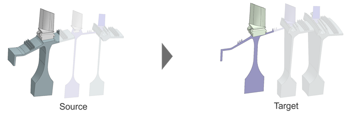
- 2D to 3D, where 2D temperatures are swept onto 3D bodies.
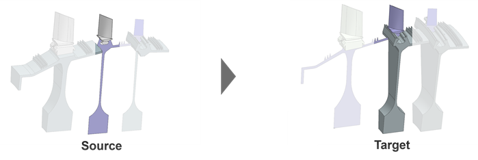
- Mixed 2D/3D bodies mapped to a 3D body, where source and target 3D
portions have different sector sizes.
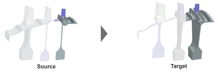
- 3D to 2D disk, where circumferentially averaged temperatures are
mapped.
- Axisymmetric mapping constraints
- You can map temperature results from a region in the source model to a
corresponding region in the target model to reduce mapping time by
eliminating unnecessary calculations in very large models.
The mapping process associates a specific source-model element with each target node or element based on closest-distance criteria controlled by zone associations.
- The source model must be a non-axisymmetric thermal model that can include both non-axisymmetric and axisymmetric meshes.
- The target model is a model that contains a solution with Analysis Type set to Mapping.
When you solve the target mapping solution, the software generates a [simulation_name]-[solution_name].bun file with the mapped thermal results on its mesh. The solution file uses a [simulation_name]-[solution_name].map file to retrieve the regions where mapping is defined in the source solution.
- Rotational periodicity mapping constraints
- If you have different 3D segment sizes between source and target that have
periodic temperatures, use the Rotational Periodicity Association
Zone and matching Rotational Periodicity Target
Zone constraints.
If circumferential offsets are required on individual rotational-periodicity zones, add them in the target constraint to circumferentially align the model.
- Mapping constraints in a 2D-3D hybrid model
-
The table below summarizes recommended mapping constraints for common mapping scenarios.
Case Mapping scenario Constraint Comments Source model/Result Target model Description Source model solution Target model solution 1 2D 2D The source and target model contain axisymmetric elements. The Thermal Association Zone type of Mapping constraint Thermal Target Zone Use separate zones to limit mapping regions, either for axisymmetric or thermal zones. The Axisymmetry Association Zone type of Mapping constraint Axisymmetry Target Zone 2 3D 2D The results from the source model, which contains 3D elements are mapped with circumferential averaging to the target model, which contains 2D axisymmetric elements. The Axisymmetry Association Zone type of Mapping constraint. Axisymmetry Target Zone Use separate zones to limit mapping regions. 3 2D 3D The results from the source model, which contains 2D axisymmetric elements are mapped with expansion to the target model, which contains 3D elements. The Axisymmetry Association Zone type of Mapping constraint. Axisymmetry Target Zone Use separate zones to limit mapping regions. 4 3D 3D The source and target models have the same number of cyclic symmetric 3D segments. The Thermal Association Zone type of Mapping constraint. Thermal Target Zone Separate mapping into different zones, if required. The Axisymmetry Association Zone type of Mapping constraint. Axisymmetry Target Zone 5 2D/3D 2D/3D The source and target models have the same number of cyclic symmetric 3D components. The Axisymmetry Association Zone type of Mapping constraint. Axisymmetry Target Zone Map 2D and 3D regions in separate zones when the regions are in contact. 6 3D 3D The source and target models have different number of cyclic symmetric 3D segments. The Rotational Periodicity Association Zone type of Mapping constraint Rotational Periodicity Target Zone 7 2D/3D 2D/3D The 2D axisymmetric component in the source model is mapped to the 3D component in the target model. The Axisymmetry Association Zone type of Mapping constraint Axisymmetry Target Zone Use axisymmetry association zone where you map 2D/3D to 2D/3D. The 3D component in the source is mapped to the 3D component in the target with different number of segments. The Rotational Periodicity Association Zone type of Mapping constraint Rotational Periodicity Target Zone Use rotational periodicity where you have 3D to 3D with different segment numbers. - Generating reference fields in ANSYS mapping solutions
- Create reference to .bun file to avoid large
node-temperature fields in a mapped ANSYS solution. This reference field
can be used in Temperature Load.Note:Reference fields can also be manually generated in post.
- Displaying the number of mapped nodes
- After solving the mapping solution, the thermal solver displays the number
of mapped nodes in the <simulation name>-<solution
name>.log file. You can inspect the log file to determine
whether any node is missing from the mapping results file.Note:
Number of target nodes to map - 15708
Number of mapped target nodes- 15708
Hands-on material
To gain experience with the topics discussed here, complete the following: