Create thermal coupling boundary conditions
Practice defining thermal coupling boundary conditions between different bodies in a model.
Open the Simulation file
Open the model Simulation file and reset the dialog box settings.
- Choose File→Open and open brake_assembly\brake_assembly_sim1.sim.
- Choose File→Preferences→User Interface and on the Dialog and Precision page, reset the dialog box memory.
-
Click OK.
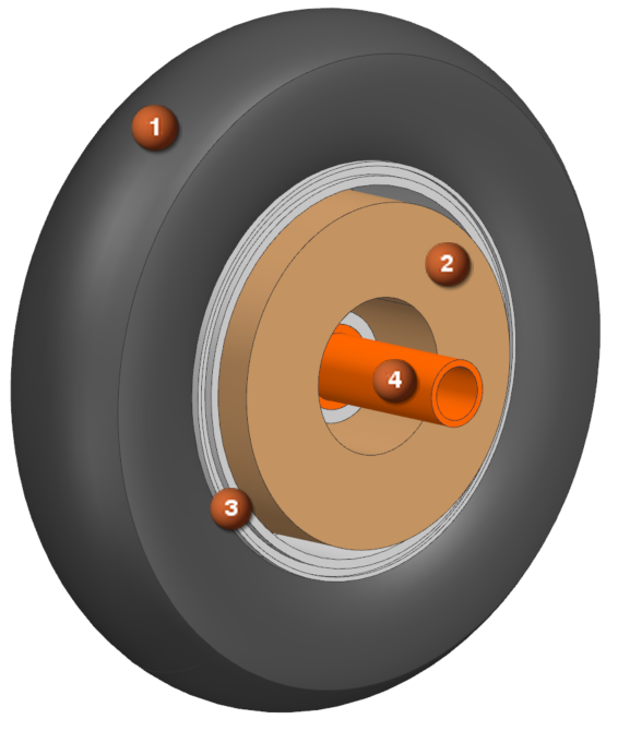
The brake assembly includes four components: tire (1), brake pad (2), wheel (3), and axle (4).
-
In the Simulation Navigator, explore existing
boundary conditions:
- Convection to environment constraints for the wheel, brake, and tire.
- Heat load of 4000 W on the brake pad surface.
Create thermal coupling between a wheel and tire
Define thermal coupling between wheel and tire with specified heat transfer coefficient.
-
Choose Home tab→Loads and
Conditions group→Simulation Object
Type list→Thermal Coupling
 .
.
- In the Name box, type Wheel_tire_TC.
- In the Simulation Navigator, expand the brake_assembly_fem1.fem → Polygon Geometry nodes and hide all the nodes except tire.
-
In the graphics window, select 2 polygon faces as shown.
-
Rotate 180 degrees, and select 2 faces on the other side.
-
In the Secondary Region group, click
Select Object
 .
.
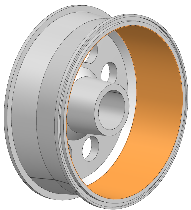
- In the Simulation Navigator, hide tire and show wheel.
-
Select 4 outer surfaces of the wheel in contact with the tire.
- In the Magnitude group, from the Type list, select Heat Transfer Coefficient.
- Set the Coefficient to 10 W/(m^2-dC) and ensure that the Only Connect Overlapping Elements check box is selected to connect each primary sub-element to the closest secondary element only if the elements overlap.
-
Click Apply.
Leave the Thermal Coupling dialog box open for the next steps.
Create thermal coupling between a brake pad and wheel
Model steady state heat conduction between brake pad and wheel with a 20000 W/m²·K heat transfer coefficient.
- In the Simulation Navigator, hide Simulation Object Container.
- In the Name box, type Brake_wheel_TC.
-
Select the wheel inner surface.
-
In the Secondary Region group, click
Select Object
.
- In the Simulation Navigator, show brake pad.
-
Select the displayed outer surface of the brake pad that is in contact with
the wheel.
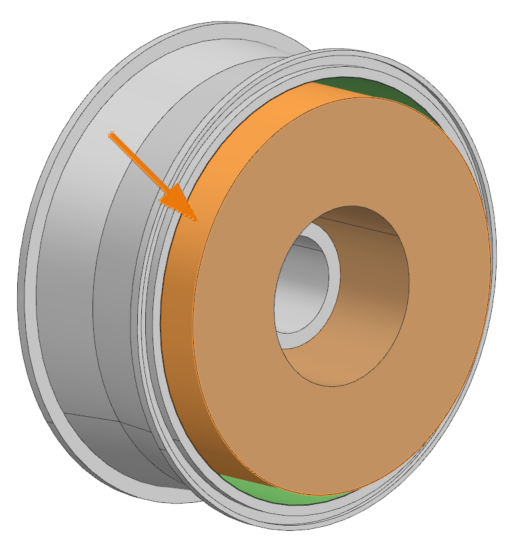
Notice that there is a gap between the brake pad and the wheel. The thermal coupling boundary condition couples the two bodies without the need to create the medium. - In the Magnitude group, from the Type list, select Heat Transfer Coefficient.
- In the Coefficient box, specify 20000 W/(m^2-dC).
-
In Additional Parameters, select Fine from Coupling Resolution.
A fine resolution is used since the mesh is coarse, and the surfaces are curved. The solver will subdivide the elements and connect only the subdivided overlapping elements.
-
Click Apply.
Leave the Thermal Coupling dialog box open for the next step.
Create additional conductance between axle and wheel
Define thermal coupling between axle and wheel with specified heat transfer coefficient.
- In the Simulation Navigator, hide Simulation Object Container.
- In the Name box, type Axle_wheel_TC
- In the Simulation Navigator, under Polygon Geometry, hide wheel and brake pad, show axle.
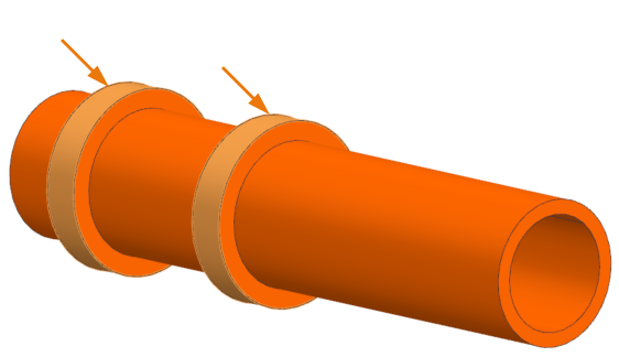
-
Select two polygon faces on axle.
- In Secondary Region, click Select Object
- In the Simulation Navigator, hide axle and show wheel.
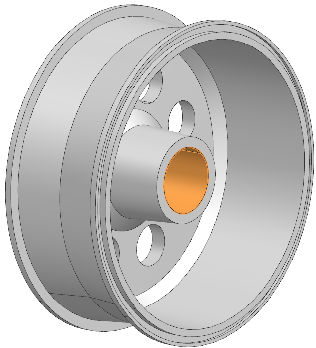
-
Select the wheel surface.
- From the Type list, select Heat Transfer Coefficient
- Set Coefficient to 20000 W/(m^2-°C).
- Click OK.
Request thermal output result sets
Set output requests to verify thermal connections during post-processing.
- In the Simulation Navigator, right-click Solution 1 in Simulation Navigator and choose Edit.
-
On the Results Options page, in the
Thermal group, select Thermal
Connections and Coupled Area Ratio
check boxes.
This allows you to view in post-processing the lines representing heat paths created by the thermal solver between primary and secondary elements of thermal couplings and the ratio of the primary element area that overlaps with secondary element selection over the primary element area, respectively.
- Click OK.
Solve the model
Solve the thermal model and monitor solution progress.
- Right-click Solution 1 in Simulation Navigator and choose Solve.
- Click OK.
- Wait for Complete status in Analysis Job Monitor.
- In the Review Results dialog, click No.
- Close the Information window.
- Click Cancel in the Analysis Job Monitor dialog.
Review results
Visualize temperature and thermal connection results using post-processing tools.
- In the Post Processing Navigator, double-click the Thermal node.
- Expand the Thermal node and double-click Temperature - Elemental node.
-
Choose Results tab → Display
group → Cutting Plane Options
 .
.
-
In the Cut Direction group, from the
Axis list, select Y

- Enter -280 in Y box.
-
Click OK.
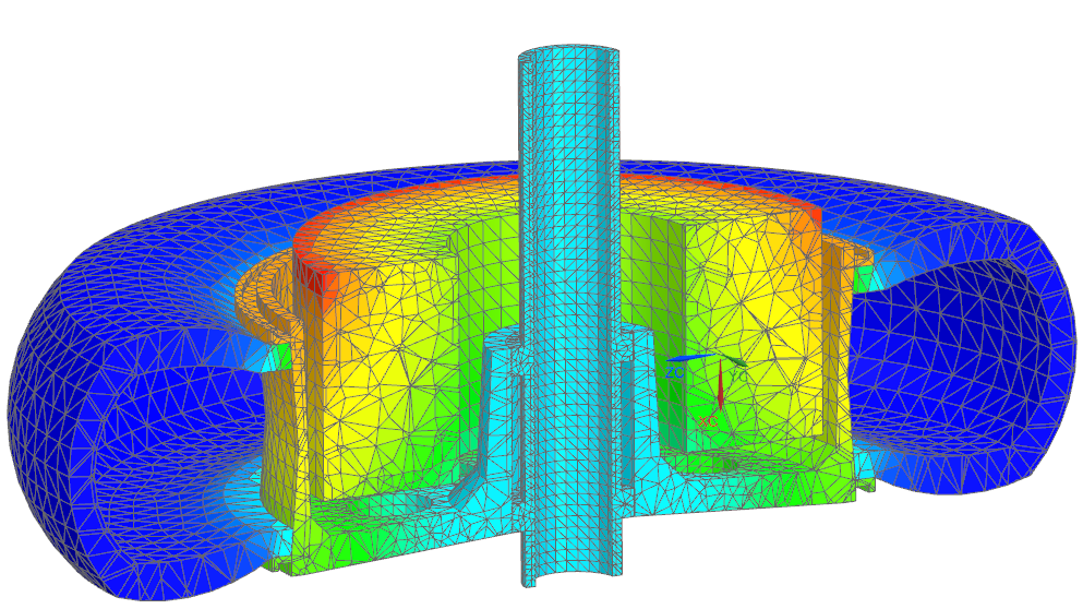
Notice that the area from the brake pad, which is not overlapped with the wheel, has the highest temperature. -
Choose Results tab→Display
group→Cutting Plane
 to turn off the cutting plane
display.
to turn off the cutting plane
display.
-
In the Post Processing Navigator, double-click
Thermal Connections - Elemental to display the
lines representing heat paths created by the thermal solver between primary
and secondary elements of thermal couplings.
Each color represents one thermal coupling. The colors are assigned randomly and cycle through 16 predefined colors. The numbers in the legend are only indicators and do not represent the coupling magnitude.
-
Choose the Results
tab→Display group→Feature
 .
.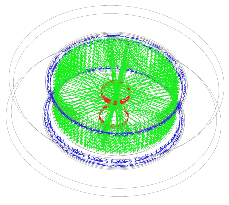
On the image, the blue color shows the connection between the wheel and the tire, the green color shows the connection between the wheel and the brake pad, the red color shows the connection between the axle and the wheel. Observe the extra connections that are created between the wheel and the brake pad. It could happen due to the gap between the selections as well as the circular geometry of the model. - In the Post Processing Navigator, double-click the Coupled Area Ratio - Elemental to display the ratio of the primary element area that overlaps with secondary element selection over the primary element area.
- Expand the Post View→Groups nodes, and double-click the Wheel_tire_TC - Elemental to display the coupled area only for the wheel to tire connection. Notice, that the ratio is equal to one, meaning that the thermal coupling is defined correctly.
-
Repeat the step 11 for other connections.
Notice that in the brake pad to wheel connection in some places the ratio is much less than 1. If we explore the geometry, we will see that in the bottom, there is no overlapping between the wheel and the brake pad, and the ratio is less than 0.5. Therefore, the thermal coupling is not correctly defined.
Modify the thermal coupling between the wheel and brake pad
Adjust coupling settings to avoid extra connections by disabling the Only Connect Overlapping Elements option. If you do not select the Only Connect Overlapping Elements check box, then thermal conductances are formed based on proximity. Each primary sub-element is connected to the closest secondary element. The connection is created based only on the distance between the elements. This will allow you to avoid extra connections between the wheel and brake pad.
-
Choose Results tab → Context
group → Return to Model
 .
.
- In Simulation Navigator, expand Simulation Objects, right-click Brake_wheel_TC and select Edit.
- In the Additional Parameters group, clear the Only Connect Overlapping Elements check box.
- Click OK and solve the model again.
Review the thermal connections
Verify thermal connections and coupling ratios post-modification.
- In the Post Processing Navigator, expand Thermal node and double-click Thermal Connections - Elemental.
-
Choose Results tab → Display
group → Feature
to view connections.
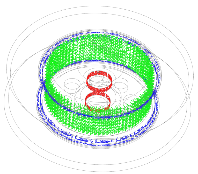
Notice that the connections are shown as expected. -
In the Post Processing Navigator,double-click the
Coupled Area Ratio - Elemental node.
Notice that the coupled area ratio is equal to 1 now, which means that the thermal connections are defined correctly.