Create multiple mesh types
Practice to mesh a CPU cooler assembly using different mesh types, such as 3D solid, 2D, or 1D beam meshes.
Open the FEM file
Open the FEM file and reset the dialog box settings.
- Choose File→Open and open cpu_cooler_esc/cpu_cooler_fem.fem.
- Choose File→Preferences→User Interface and on the Dialog and Precision page, reset the dialog box memory.
Mesh the copper plate using a 2D mesh
Mesh the copper plate using a 2D mesh.
-
Choose Home tab→Mesh
group→2D Mesh
 .
.
-
In the graphics window, select the top face of the cooler plate, as
shown.
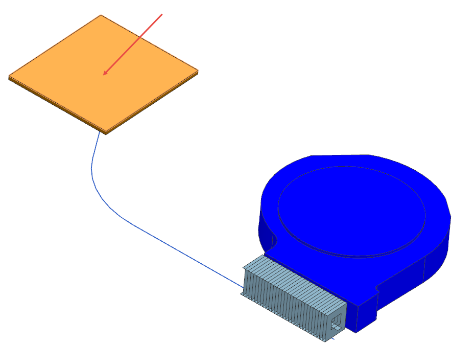
- In the Element Properties group, from the Type list, select QUAD4 Thin Shell.
- In the Mesh Parameters group, in the Element Size box, specify 4 mm.
- Clear the Automatic Creation check box.
- Click OK.
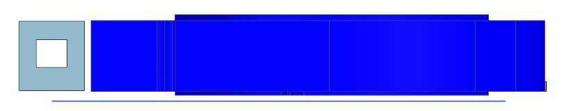
Mesh the heat sink using a 2D mesh
Mesh the heat sink using a 2D mesh.
-
Rotate the model and press F8 to orient the work view to the nearest
orthographic view.
-
Choose Home tab→Mesh
group→2D Mesh
.
- In the Top Border bar, from the Type Filter list, select Polygon Face.
-
Select all 120 heatsink faces.
- Note that Type list is now set to QUAD4 Thin Shell.
- In the Mesh Parameters group, in the Element Size box, specify 0.4 mm.
- In the Destination Collector group, from the Mesh Collector list, select heatsink collector.
- Click OK.
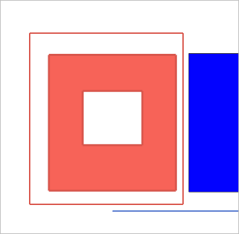
Mesh the air volume using a 3D mesh
Mesh the air volume using a 3D mesh.
-
Choose Home tab→Mesh
group→3D Tetrahedral Mesh
 .
.
-
Select the polygon body as shown.
- In the Element Properties group, from the Type list, select TET4.
- In the Mesh Parameters group, in the Element Size box, specify 2 mm.
- Clear the Automatic Creation check box.
- Click OK.
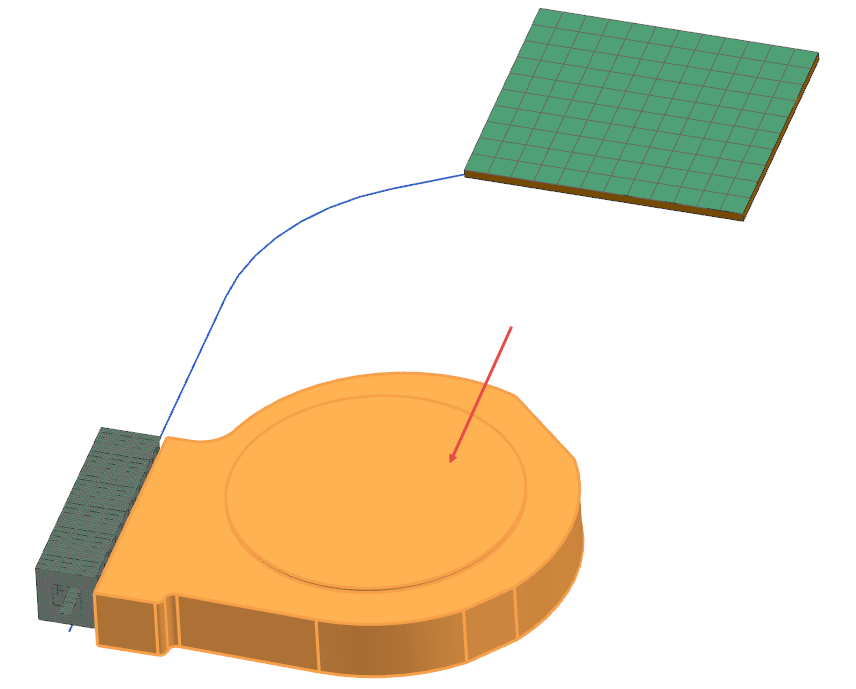
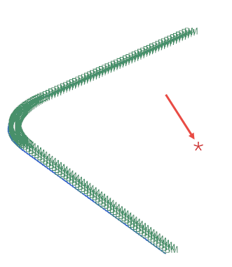
Mesh the heat pipe with beams
Mesh the heat pipe with beams.
- In the Simulation Navigator, hide Polygon Geometry, 2D Collectors, and 3D Collectors nodes.
-
Choose Home tab→Mesh
group→1D Mesh
 .
.
- Select the Auto Chain Selection check box.
-
Select the three curves as shown.
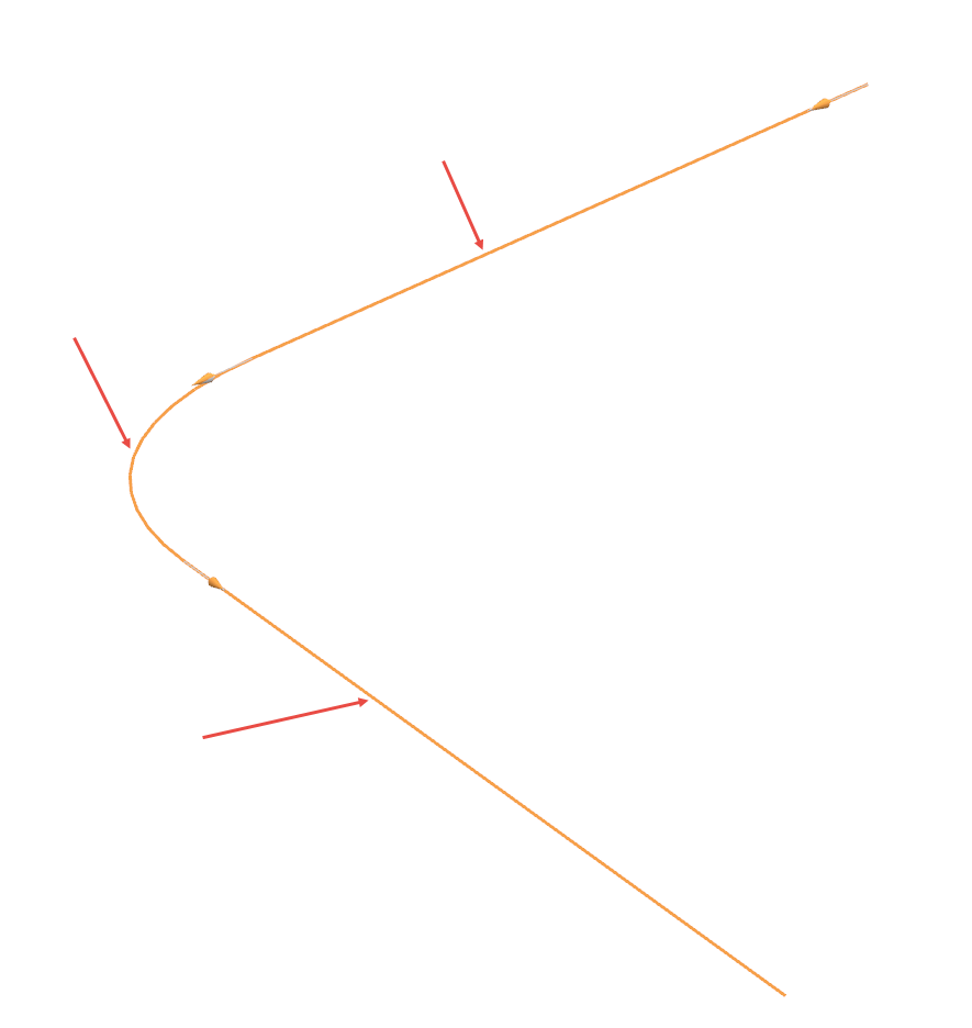
- In the Element Properties group, make sure that the Type list is set to Beam.
- In the Mesh Parameters group, in the Number of Elements box, specify 50.
- Select the Merge Nodes check box.
- Clear the Automatic Creation check box.
- Click OK.
- In the Simulation Navigator, expand the 1D Collectors→heatpipe collector nodes.
- Right-click the 1d_mesh(1) node and choose Edit Display.
- Select the Text check box to display the label for 1D elements.
- Click OK.
Create a node
Create a node for a 0D mesh.
-
Choose Nodes and Elements
tab→Nodes group→Node
Create
 .
.
- In the Location group, in the Y box specify -50.
- Click OK.
Create a 0D mesh on the node
Create a 0D mesh, which you can use to specify concentrated mass for a thermal analysis.
-
Choose Nodes and Elements
tab→Elements group→Element
Create
 .
.
- In the Element Family group, select 0D.
-
Select the created node as shown.
- Click Close.