Analyze diurnal heating of a rover
Practice to model the thermal effects of the sun on a rover during a day.
Open the Simulation file
Open the model Simulation file and reset the dialog box settings.
- Choose File→Open and open mars_rover\mars_rover.sim.
- Choose File→Preferences→User Interface and on the Dialog and Precision page, reset the dialog box memory.
- Click OK.
Check the material properties
Check the material properties for all elements in the enclosure. To model diffuse radiation within the enclosure, all elements must have emissivity defined. For solar spectrum radiative heating, all elements must have solar absorptivity defined.
- In the Simulation Navigator, right-click the mars_rover_fem.fem node and choose Make Work Part.
- Expand the mars_rover_fem.fem → 2D Collectors nodes.
- Under the 2D Collectors node, right-click the Rover_structure node and choose Edit.
- In the Thermo-Optical Properties subgroup, click Edit.
- Verify that Emissivity and Absorptivity are defined.
- Click Cancel twice.
- Repeat the steps 3-6 for the rover_wheels, ground, antenna, and solar_panel_collector nodes.
Define solar heating
Use the Solar Heating Space simulation object to calculate solar view factors for extended periods of time. You will position the rover on the surface of Mars at latitude of 40º. You will align the rover front to face south, and the opposite side of the antenna to face east.
- In the Simulation Navigator, right-click the mars_rover.sim and choose Make Work Part.
-
Choose Home tab→Loads and
Conditions group→Simulation Object
Type list→Solar Heating Space
 .
.
- From the Type list, select Illuminate Selected Elements to limit the solver's search for illuminated elements to only the elements you select.
-
In the Top Side Illuminated Region group, click Region Illuminated on Top Side
 .
.
- On the scene toolbar, from the Method list, select Faces by Group.
-
In the Simulation Navigator, expand the
Groups node, select exposed faces
1 and exposed_surfaces_2.
175 faces are now selected.
- In the Parameters group, from the Planet list, select Mars.
- In the Latitude box, type 40 degrees.
-
From the Element Subdivision list, select
1 granularity level of the element subdivision
for computing shadowed view factors to reduce computation time.
A higher subdivision level yields more accurate radiative conductances, but the computation requires additional time.
- On the Model Orientation tab, in the Planet Vectors group, click Specify Vector.
- On the Top border bar, from the Type Filter list, select Polygon Edge.
-
Select the edge as displayed.
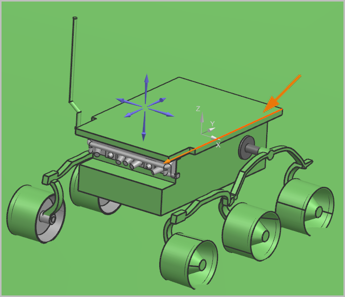
-
Click Reverse Direction
 , if the direction is displayed
differently.
, if the direction is displayed
differently.
- From the Aim at list, select South.
- Click Specify Vector.
- On the Top order bar, from the Type Filter list, select Polygon Edge.
-
Select the edge as displayed.
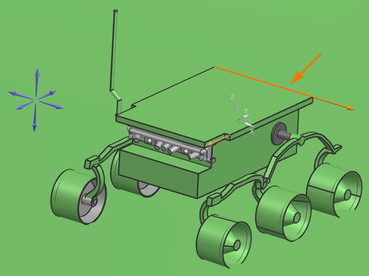
-
Click Reverse Direction
, if the direction is displayed
differently.
-
From the Align with list, select
East.
Leave the dialog box opened.
Set the solar heating time frame
Set the number of points between sunrise and sunset at which the software calculates solar heating.
- In the Solar Heating Space dialog box, on the Model Orientation tab, in the Solar Vectors group, from the Day Segment list, select Partial Day.
- In the Start Angle from Midnight box, type 100 degrees.
- In the Final Angle from Midnight box, type 280 degrees.
- In the Number of Equal Angular Intervals box, type 20.
- On the Solar Flux tab, in the Sun Right Ascension box, type 30 degrees.
- Click OK.
- In the Simulation Navigator, expand the Simulation Object Container node, right-click the Solar Heating Space(1) node, and choose Edit Display.
- In the Symbols group, move the Scale slider to Tiny.
- Click OK.
Define a radiation enclosure for the rover
Consider the radiative heat exchanges between the rover, ground and ambient temperature by adding them to an enclosure.
-
Choose Home tab→Loads and
Conditions group→Simulation Object
Type list→Radiation
 .
.
- Make sure that Enclosure Radiation is selected from the Type list.
- On the scene toolbar, from the Method list, select Faces by Group.
-
In the Simulation Navigator, select
exposed faces 1 and
exposed_surfaces_2.
175 faces are selected.
-
In the Parameters group, make sure that the
Include Radiative Environment check box is
selected to model radiative exchange between any part of the enclosure and
the environment.
You must also define a radiative environment temperature in the solution's global ambient conditions.
- Make sure that the Element Subdivision list is set to 3.
- Click OK.
- In the Simulation Navigator, under the Simulation Object Container node, hide Radiation(1).
Set the parameters for a transient solve
Diurnal heating is a transient phenomenon, you will consider the ambient temperature change between sunrise and sunset. The surface temperatures for the first three mission days that are obtained from sensors located on the metrological mast are provided on the following curves.
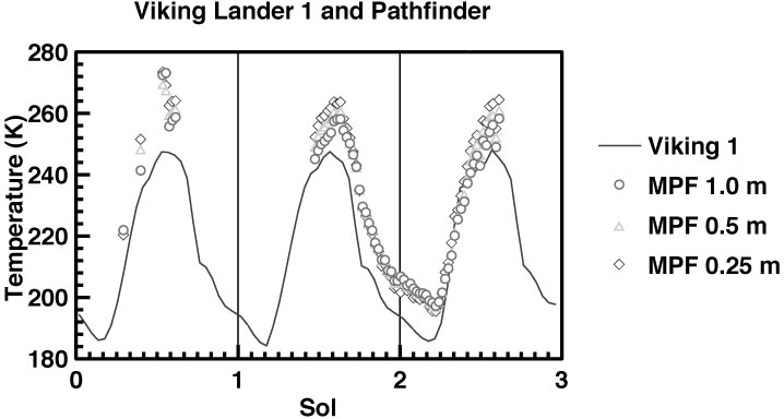
Source: http://mars.jpl.nasa.gov/MPF/ops/ss008.jpg
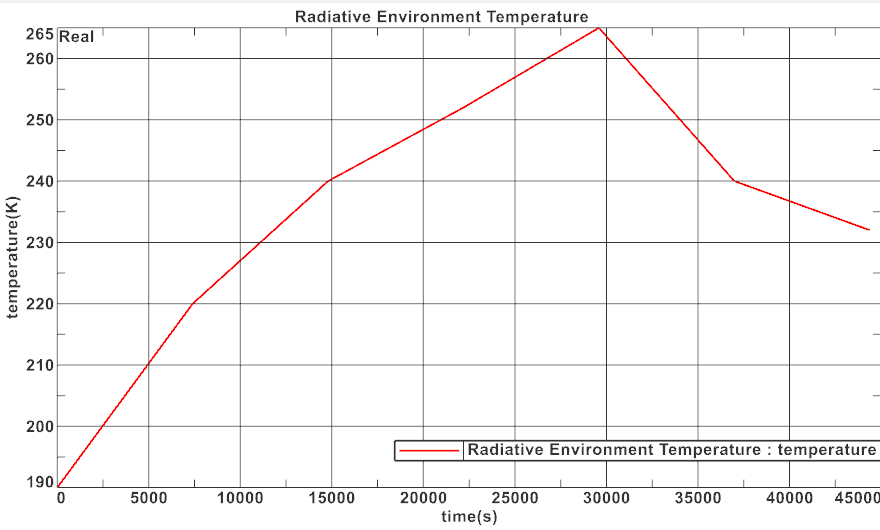
| Simulation time (Seconds) | Time of day (Sol in Seconds) | Ambient temperature (K) |
|---|---|---|
| - | 0 | 205 |
| 0 | 22192 | 190 |
| 7390 | 29590 | 220 |
| 14769 | 36988 | 240 |
| 22194 | 44386 | 252 |
| 29590 | 51782 | 265 |
| 36988 | 59180 | 240 |
| 44385 | 66577 | 232 |
| - | 73976 | 212 |
| - | 88770 | 205 |
- In the Simulation Navigator, right-click the Day 1 node, and choose Edit.
- On the Solution Details page, in the Solution Type group, from the Solution Type list, select Transient.
- On the Transient Setup page, make sure that the End list is set to At Specified Time.
- In the End Time box, type 44385 sec.
- In the Time Integration Control group, in the Number of Time Steps box, type 500.
-
On the Ambient Conditions page, in the Pressure and Temperature group, next to the Radiative Environment Temperature box, click
 and choose New Field→Table.
- On the Independent Domain page, from the Independent list, select Time.
-
On the Definition page, click Import from
Text File
 .
.
-
In the Table Data Import dialog box, click Browse
 and select Mars_ambient_temperature_data_CSV.csv.
- Click OK twice.
- To change the temperature units to Kelvin, in the Table Field dialog box, right-click the temperature (°C)* table column heading and choose Change Units for Variable→K.
- Click OK.
-
To display the radiative temperature graphic, next to the
Radiative Environment Temperature box, click
 and select Plot (XY)
 .
.
- Click OK.
-
Click on the graphics window.
- Click OK.
Solve the model
- In the Simulation Navigator, right-click the Day 1 node and choose Solve.
- Click OK.
- Wait for the solve to end, before proceeding.
- In the Review Results dialog box, click No.
- Close the Information window.
- In the Analysis Job Monitor dialog box, click Cancel.
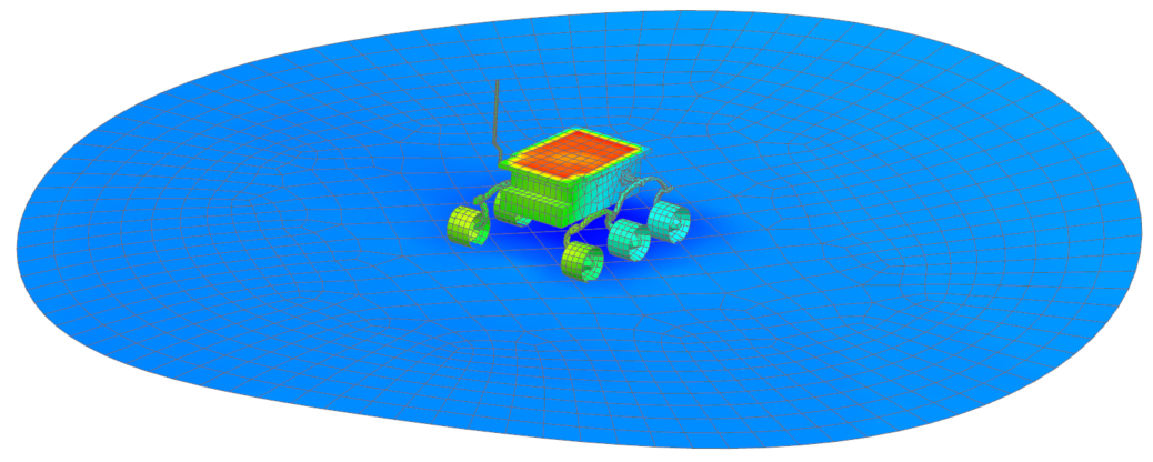
Display temperatures and animate absorbed radiative flux
Visualize the temperature distribution on the rover during one day.
- In the Simulation Navigator, under the Day 1 node, double-click Results.
-
In the Post Processing Navigator, expand
Thermal → Increment 28,
2.959E+04s, and double-click Temperature -
Nodal.
- In the Post Processing Navigator, expand Increment 1, 0 s, and double-click Absorbed Radiative Flux, SUN - Elemental.
-
Choose Results tab→Post View
group→Edit Post View
 .
.
- On the Result tab, in the Result Combination group, from the Combine At list, select Nodes.
- Make sure that the Nodal Combination is set to Average.
- Click OK.
-
Choose Results tab→Animation
group→Animate
 .
.
- From the Animate list, select Iterations.
-
Click Play.
Notice how the absorbed radiative flux changes during the day.
- Click Stop.