Use Simcenter 3D files in an analysis
Practice the workflow for using Simcenter 3D files as you are analyzing a model.
Open the part file and set up user preferences
Open the part file and reset the dialog box settings.
-
On the Resource bar, click the Roles
 tab.
tab.
- In the Roles palette, in the Content folder, select the Advanced role.
- Click OK.
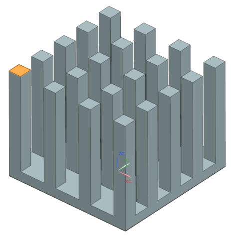
- Choose File→Open and open heatsink/heatsink.prt.
- Choose File→Preferences→User Interface and on the Dialog and Precision page, reset the dialog box memory.
Create Simulation and FEM files
Create Simulation and FEM files.
-
Choose Application
tab→Simulation
group→Pre/Post
 .
.
Work with multiple tabbed windows
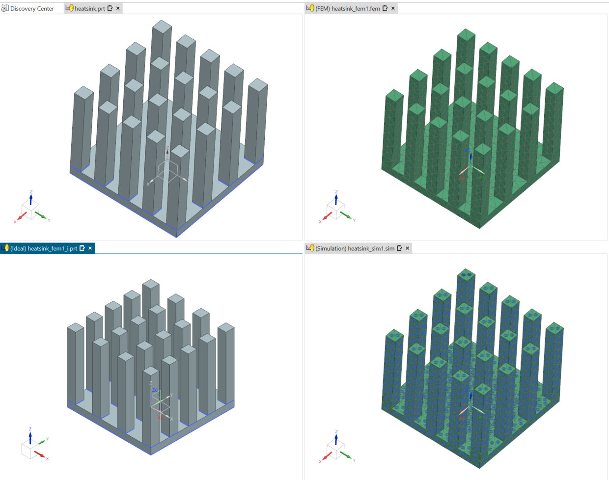
Change the window layout. The part that is saved to each file such as part, FEM, and Simulation is displayed in its own tabbed window. Idealized part is not opened in a tab by default.
-
Click and hold on the tab for the FEM file and drag it towards the center
of the graphics window to activate the docking controls. Place the cursor
over the right arrow.
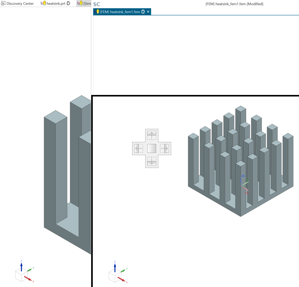
-
Click and hold the tab for the Simulation file and drag it towards the
center of the right window. Place the cursor over the bottom arrow of the
docking controls to position the Simulation file window in the lower-right
of the graphics window. Your view should look like the following
image.
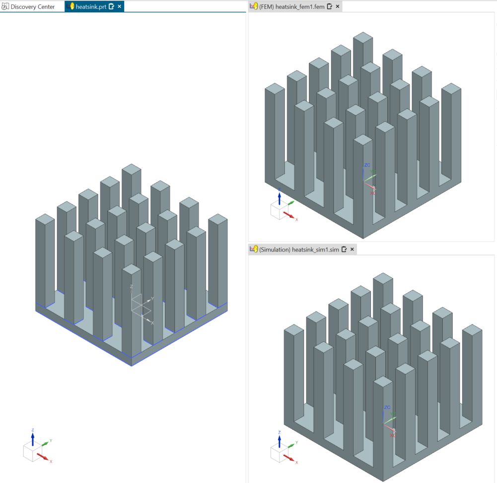
- Use the middle mouse button in each of the windows to rotate the model in that window. Each window is independent of the other windows.
-
Choose Results tab→View
Layout group→Synchronize Views
 to synchronize the orientation and zoom level
of selected viewports.
to synchronize the orientation and zoom level
of selected viewports.
-
Select all windows and click
 .
.
- Try to rotate and zoom out the model.
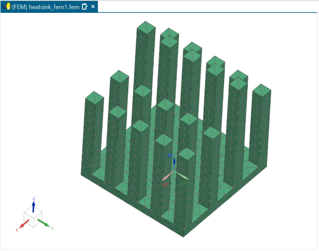
Mesh the model
Mesh the model with a 3D tetrahedral mesh.
-
Choose Home tab→Mesh
group→3D Tetrahedral
 .
.
-
In the Destination Collector group, click
New Collector
 .
.
-
In the Mesh Collector dialog box, click
Create Physical
 .
.
-
In the Properties group, click Choose
material
 .
.
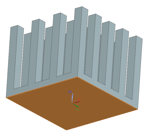
Add boundary conditions
Apply a thermal load, temperature constraint, initial conditions, and convection to environment boundary conditions.
-
Choose Home tab→Loads and
Conditions group→Load
Type→Thermal Loads
 .
.
-
Select the shown face.
-
Choose Home tab→Loads and
Conditions group→Constraint
Type→Temperature
 .
.
-
Select the shown face.
-
Choose Home tab→Loads and
Conditions group→Constraint
Type→Convection to Environment
 .
.
-
Select the shown faces, except the face on which you applied the thermal
load.
Tip: To deselect the face, press Shift and select the face you want to exclude.

87 faces are selected.
-
Show
 the 3D Collectors
again.
the 3D Collectors
again.
Open the idealized part
Open the idealized part.
Promote the idealized part and reposition the idealized part window
Promote the idealized part and reposition the idealized part window.
-
Choose Home tab→Start
group→Promote
 .
.
-
Click and hold on the tab for the idealized part and drag it towards the
left of the graphics window. Place the cursor over the bottom arrow of the
widget to position the idealized part window in the lower left of the
graphics window.
Your graphics window should show four equal sized windows containing the master part, idealized part, FEM file, and Simulation file.
Modify the idealized part geometry
Modify the idealized part by removing a pocket. You are going to work in the idealized part window in the lower left of the graphics window to perform these steps.
-
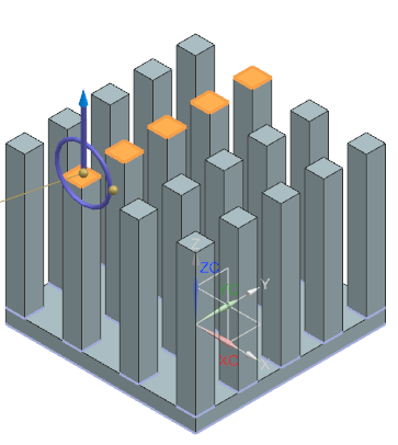
Choose Home tab→Synchronous
Modeling group→Move
 .
.
-
In the idealized part file window, select the five faces as shown.
-
In the Distance box, type 30
mm and press Enter.
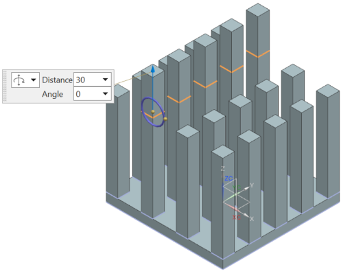
- Click OK.
Explore how changes affect other files
Explore how changes to the idealized part affect the other Simulation files.
-
Choose Home tab→Context
group→Update
 .
You can see that the remeshed part reflects the modified idealized part.
.
You can see that the remeshed part reflects the modified idealized part.