Slip wall treatments for gases
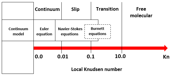
For the flow regimes at low absolute pressure or in gas flows involving micro-channels, where the Knudsen number Kn is small, the no-slip boundary condition is no longer valid. The flow solver uses slip wall treatment for gas flows with Knudsen numbers ranging from 0.01 to 0.1:
where
- L0 is the characteristic length of the flow.
- λ is the mean free path of the gas.
This regime is referred to as the slip regime, [43].
Within this regime, the flow solver uses the standard momentum and energy equations to model the gas flow with the following modifications to the boundary treatments:
- The velocity has a non-zero finite value, called slip velocity.
- Thermal creep effects can be taken into account.
- The gas temperature at the wall can be different from the wall temperature. There can be a temperature jump at the wall.
Slip velocity
The flow solver uses a second order extension of Maxwell’s model [44] to approximate the slip velocity. The traditional no-slip boundary condition is relaxed to allow the rarefied gas to slip at the wall by imposing a tangential component of the slip velocity at the solid boundary. The expression of the slip velocity is defined as:
where:
- Us is the slip velocity.
- Uw is the wall velocity.
- n is the local normal direction of the wall.
- C1 and C2 represents respectively the first-order and second-order slip coefficients.
To impose the Maxwell model to all walls that have slip wall specified, use the
USE LOW-PRESSURE MAXWELL SLIP WALL TREATMENT advanced
parameter. This advanced parameter replaces the standard slip wall treatment by the
Maxwell model.
By default, C1 = 1 and C2 =
0. You can specify them using the MAXWELL SLIP WALL C1 and
MAXWELL SLIP WALL C2 advanced parameters.
You have to
enable the Velocity Adjusted result set to view the results
for the slip velocity. You can view the results in the
slipValues.dat output file located in the run directory
when you specify the OUTPUT LOW-PRESSURE MAXWELL SLIP WALL SUMMARY
advanced parameter.
Thermal creep effect
The Maxwell's model with included thermal creep effect, induced in rarefied flow with large tangential wall temperature gradient is given by:
where
- γ is the specific heat ratio defined as γ = cp/cv, where cp is the specific heat at constant pressure and cv is the specific heat at constant volume.
- T is the absolute temperature of the gas.
- s is the local tangential direction of the wall.
- μ is the dynamic viscosity of the gas.
- ρ is the density of the gas.
You can include the thermal creep effect only in the case of a non-isothermal
fluid using the INCLUDE THERMAL CREEP TERM IN MAXWELL MODEL
advanced parameter.
Temperature jump
The flow solver uses a temperature jump condition derived by von Smoluchowski [45] to account for the effect of gas temperature. The temperature jump expression is defined as:
where
- Ts is the slip temperature of the gas.
- Tw is the wall temperature.
- σT is the thermal accommodation coefficient.
- is the Prandtl number.
- k is the thermal conductivity of the gas.
To impose the Maxwell low-pressure temperature jump model, use the USE
LOW-PRESSURE MAXWELL TEMPERATURE JUMP TREATMENT advanced parameter. By
default, the value for the thermal accommodation coefficient is 1. You can modify it
using the MAXWELL SLIP WALL SIGMA T advanced parameter. Use the
OUTPUT LOW-PRESSURE MAXWELL SLIP WALL SUMMARY advanced
parameter to view the results in the slipValues.dat output file
located in the run directory.
Mean free path of the gas
The mean free path of the gas is calculated locally at every wall-adjacent element by using the local gas density, pressure, and temperature.
where
- T0 is the specified reference temperature of the gas. You
specify it using the
REFERENCE TEMPERATURE FOR SLIP CORRECTIONadvanced parameter. - P0 is the specified reference pressure of the gas. You specify
it using the
REFERENCE PRESSURE FOR SLIP CORRECTIONadvanced parameter. - S is the specified Sutherland constant for the viscosity of the gas. You
specify it using the
SUTHERLAND CONSTANT FOR SLIP CORRECTIONadvanced parameter. - λ0 is the reference mean free path of the gas at temperature T0 and pressure P0, given by the following equation:
- μ0 is the reference viscosity of the ideal gas. You specify it using
the
REFERENCE VISCOSITY FOR SLIP CORRECTIONadvanced parameter. - ρ0 is the reference density of the ideal gas, which is calculated using ideal gas law.
- kB is the Boltzmann constant.
- η is the Avogadro's number.
- R = 8.31434 (J/mol) is the universal gas constant.
- Rg is the specific gas constant, which is obtained from the gas material properties.