Mixing plane
A mixing plane boundary condition interfaces two or more fluid volumes with different flow conditions.
The two interfacing faces:
- Can have different geometries.
- Can have a connected interface or be geometrically separated.
- Do not need to be parallel.
The algorithm solves each fluid volume independently. It uses flow variable values from the adjacent fluid volume as boundary conditions.
You can use a mixing plane on two or more interfacing faces with different geometries. The interfacing faces are subdivided in a number of areas you specify. The areas are matched to its closest corresponding area according to their geometry and the averaging method you choose.
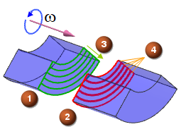
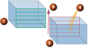
| Averaging method examples | |
|---|---|
|
|
|
(1) Upstream (2) Downstream |
(3) Averaging direction (4) Number of segments—in these examples: 5 segments |
For each area, the averaged flow variables are transformed to a 1D field using an averaging technique and the information is applied to the other side as a boundary condition.
Depending on the flow direction, for the momentum equation along each area, the downstream static pressure is applied to the upstream side, whereas the total pressure of the upstream side is applied to the downstream side in an explicit order.
The values are mapped between areas to account for different geometry and mesh size at the interfaces.
You define either a radial or axial averaging method.
- When the defined axis is perpendicular to the mixing plane, the flow variable values are averaged along radial arcs at the interfaces.
- When the defined axis is parallel to the mixing plane, the flow variable values are averaged perpendicular to axial segments at the interfaces.