Rotating frames of reference
The flow solver uses the frozen rotor method for rotating frames of reference (RFR). This method is useful for models where the flow distribution around the interface between the fixed and the rotating frames is non-uniform.
The flow solver uses the following Navier-Stokes and Energy equations that use the absolute velocity formulation. In order here are the mass, momentum, and total energy conservation equations.
where:
- is the absolute (inertial) velocity.
- is the relative velocity in the rotating frame.
- is the rotating frame velocity relative to the inertial reference frame.
- is the angular frame velocity.
- is the position vector from the origin of the rotating frame.
- H is the total enthalpy.
The interface between the frames allows the flow solver to model the frame change with a zero head loss and the flow recirculation across the interface.
The following figure is a schematic representation of the RFR interface with coupled nodes and the control volumes. These nodes are physically at the same location but not in the same frame of reference.
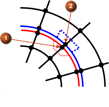
(1) The attached node to rotating frame 1 with rotational velocity .
(2) The attached node to rotating frame 2 with rotational velocity .
At the RFR interface, the flow variables, such as absolute velocities and static pressure, and the total enthalpy are equal between node 1 and node 2: