VVC7 - Natural convection between eccentric cylinders
| Test case |
|---|
| SVTEST100 |
Description
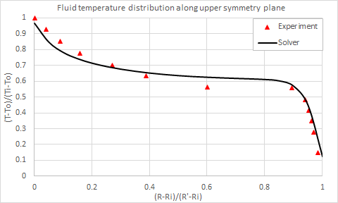
This case examines natural convection between eccentric cylinders of infinite length, and compares the fluid temperature distribution predicted by the solver, with experimental data obtained by Kuehn and Goldstein [41].
Geometry
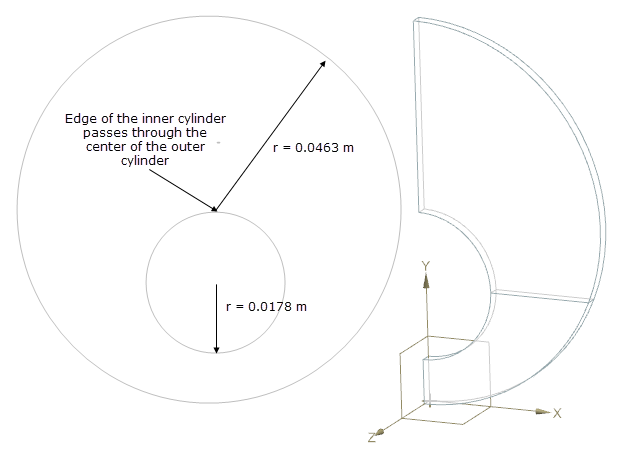
The geometry consists of eccentric cylinders. The radius of the inner cylinder is 17.8 mm and the outer cylinder is 46.3 mm. The edge of the inner cylinder passes through the center of the outer cylinder, as shown on the following figure (left). The geometry in this model is symmetric along the middle vertical YZ plane. One half of the eccentric cylindrical system is modeled. The flow between the cylinders is assumed to be two-dimensional, since the cylinders are of infinite length. The solid used to determine the model consists of two solid volumes, which are defined through a septum in the XZ plane as shown on the following figure (right).
Simulation model
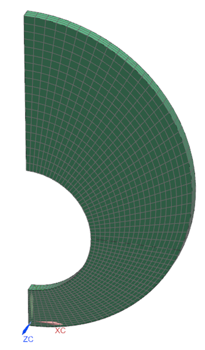
Both solid volumes, which represent the air between the eccentric cylinders, are meshed with solid hexahedral elements. Each volume is mapped with the same amount of elements:
- 20 elements along the radial direction
- 30 elements on the cylinder edge (each quater)
- 3 elements through the thickness
The following fluid properties are used:
- Mass density: ρ = 1.204 kg/m3
- Thermal conductivity: k = 0.0263W/m·K
- Thermal expansion coefficient: β = 3.41 × 10⁻³K−1
- Specific heat at constant pressure: Cp = 1007J/kg·K
- Gas constant: R = 287J/kg·K
- Dynamic viscosity: µ = 1.85 × 10⁻⁵ kg/m·s
The following boundary conditions are applied:
- Flow Surface: Boundary Flow Surface on the both cylinders, using the No Slip Wall option with smooth wall friction and convection properties set to Automatic.
- Symmetry on the middle vertical YZ plane, and the other two on the XY plane.
- Temperature constraint: on the inner cylinder with a value of 373 K, and on the outer cylinder with a value of 351.784 K.
The following non-default solver options are used:
- Turbulence Model: None (Laminar Flow)
- Solution Type: Steady State
- Buoyancy: Selected
- Ambient Conditions: Fluid temperature = 293.15 K, ambient pressure 0.101351 MPa, gravity vector -Y, gravitational acceleration = 9.81 m/s2
The following non-default solver parameters are used:
- 3D Flow Solver: Physical steady-state with time step = 0.5 s
- 3D Flow Solver: Maximum Residuals = 1e-6
- 3D Flow Solver: Buoyancy Model=Boussinesq
- Coupled Solver: Max temperature change = 0.1 ΔºC
- Coupled Solver: Global imbalance fraction = 0.01
Theory
The local heat transfer coefficient on inner and outer cylinder are given by:
where:
- qwi is the heat flux on the inner cylinder.
- qwo is the heat flux on the outer cylinder.
- Ti is the inner cylinder temperature.
- To is the outer cylinder temperature.
The local equivalent conductivity for inner and outer cylinders are calculated by:
where:
- Di is the inner cylinder diameter.
- Do is the outer cylinder diameter.
Results
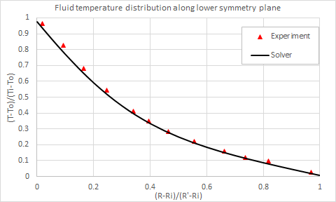
The following figures compare the fluid temperature along the lower and upper symmetry planes, computed by the solver, with the experimental data of Kuehn and Goldstein [41].
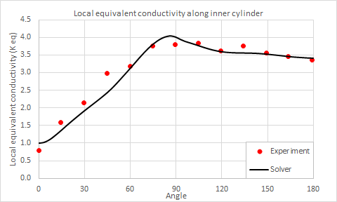
The following figures compare the local equivalent conductivity along the inner and outer cylinder walls, computed by the solver, with the experimental data of Kuehn and Goldstein [41].
