VVC3 - Incompressible laminar heated pipe flow (Graetz problem)
| Test case |
|---|
| SVTEST28 |
Description
This test case examines the problem of a developing temperature profile in a pipe, due to a sudden change in a wall temperature. It is assumed that the fluid temperature is uniform until the sudden change is reached. The following figure presents the problem to be modeled, where Tw is the wall temperature, T0 is the uniform fluid temperature before the sudden change, T is the fluid temperature, x is the axial position in the pipe, u the axial velocity component and r is the radius along the pipe.
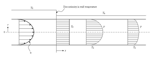
The flow is considered fully-developed, therefore its u velocity profile is assumed to obey Poiseuille’s solution:
where Uavg is the mean u velocity and R is the radius of the pipe. The Nusselt number on the heated surface of the pipe is compared to Graetz solution.
Geometry
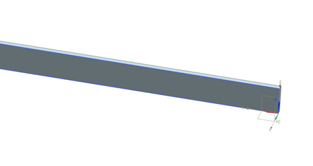
The geometry from which the mesh is produced consists of a rectangular slab with length 2000 mm, width 2 mm, and height 10 mm. The following figure shows the geometry used to create the pipe mesh.
Simulation model
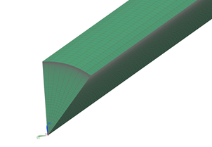
The X-Z surface of the prism is meshed using a mapped mesh of quadrilateral elements. The following mesh controls are used on the rectangle surface:
- Height: 60 elements, 1.06 bias
- Length: 300 elements, no bias
The revolved mesh is used to create the arc pipe using hexahedral elements. The following settings are used:
- Number of Copies = 5
- Axis of revolution = X axis
- Point of revolution = (0,0,-0.01)
- Angle = 5◦ per copy
The resulting 3D mesh consists of 144,000 hexahedral elements and 165,249 nodes.
The fluid is modeled using water with the following properties:
- Mass density: ρ = 1000 kg/m3
- Thermal conductivity: k = 0.603 W/m·C
- Dynamic viscosity: µ = 1.006e-3 Pa·s
- Specific heat at constant pressure: Cp = 4187 J/kg·K
The following boundary conditions are applied:
- Flow Boundary Condition: Inlet Flow on the front of the prism with the velocity profile defined by a spatial field using cylindrical coordinates and ambient external conditions
- Flow Boundary Condition: Opening on the opposite side of the prism
- Flow Surface: Boundary Flow Surface on the bottom walls of the arc pipe using the Slip Wall option
- Flow Surface: Boundary Flow Surface on the top of the arc pipe using the No Slip Wall option with smooth wall friction and Convection Properties set to Automatic
- Periodic Boundary Condition on the radial walls of the arc pipe with the axis of revolution in the X direction
- Temperature constraint on the top of the arc pipe with a value of T = 0 °C
The following solution options are set:
- Turbulence Model: None (Laminar Flow)
- Ambient Conditions: Ambient Pressure Value = 0.101351 MPa
- Ambient Conditions: Fluid Temperature = 40 °C
- 3D Flow: Reference Temperature = 40 °C
- Results Options: Select the Local and Bulk Convection Coefficients check box.
The following solver parameters are selected:
- 3D Flow Solver: Maximum Residuals =1e-6
- 3D Flow Solver: Mass relaxation factor = 0.5
- 3D Flow Solver: Fluids relaxation factor = 0.5
Theory
The theory of Graetz 8 is used as a basis of comparison for the solver results. In particular, the Nusselt number can be expressed in the form of an infinite series:
where:
- Nux is the Nusselt number.
- hx is the convection coefficient (based on the mean fluid temperature).
- d is the diameter of the pipe.
- k is the thermal conductivity of water.
- λn are Graetz’s eigenvalues.
- Cn are Graetz's eigenvalues associated constants.
The first 10 values are contained in the following table:
| n | λn | Cn | – Cnf'n(1) |
|---|---|---|---|
| 0 | 2.7043644 | +1.46622 | 1.49758 |
| 1 | 6.679032 | -0.802476 | 1.08848 |
| 2 | 10.67338 | +0.587094 | 0.92576 |
| 3 | 14.67108 | -0.474897 | 0.83036 |
| 4 | 18.66987 | +0.404402 | 0.76474 |
| 5 | 22.67 | -0.35535 | 0.71571 |
| 6 | 22.67 | +0.31886 | 0.67798 |
| 7 | 30.67 | -0.29049 | 0.64711 |
| 8 | 34.67 | +0.26769 | 0.62119 |
The dimensionless pipe’s axial position x* is computed as:
where:
- Re is the Reynolds number based on the pipe’s diameter.
- Pr is the Prandtl number of water.
The Nusselt number is based on the mean fluid temperature Tm, which varies along the pipe’s length as:
where the dimensionless mean fluid temperature is defined as :
where:
- Tw is the pipe wall temperature after the sudden change.
- T0 is the inlet fluid temperature.
To compute the bulk heat transfer coefficient based on the varying mean fluid temperature Tm, the following transformation is applied:
where:
- Ts is the theoretical mean fluid temperature.
- Tb is a bulk heat transfer coefficient.
Results
The Nusselt number results are compared in the following figure.
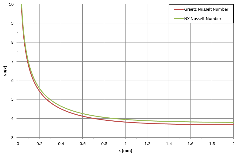
The software predicts a constant Nusselt number of 3.80 at the end of pipe while the analytical value is 3.66.
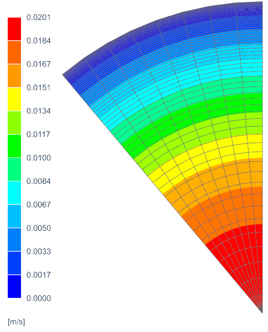
The average velocity is 0.01 m/s. The following figure shows the velocity profile plot contour.
