VVC5 - Incompressible laminar heated flow over a cylinder
| Mesh | Test case |
|---|---|
| Coarse | SVTEST57 |
| Medium | SVTEST58 |
| Fine | SVTEST59 |
Description
This study examines the transient (but periodic-steady) laminar flow over a circular heated cylinder of uniform cross-section with the following characteristics:
- ReD = 100
- Pr = 1
The Reynolds number, ReD, based on the diameter, D, was selected to correspond to a two-dimensional flow and has periodic vortex shedding capabilities. The Prandtl number, Pr, is representative of many gaseous materials.
Geometry
The geometry is made up of an extruded rectangular fluid domain with a cylindrical cavity. The diameter D of the cylindrical cavity is 1 m and the length of the calculation domain in the Z-dir is also 1 m.
Simulation Model
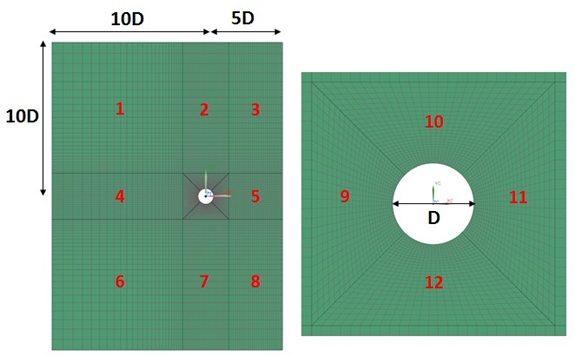
The mesh is made of hexahedral elements using the swept mesh command. The calculation domain is partitioned into 12 sections as shown in the following figure.

The computational domain behind the cylinder was intentionally truncated to a length of 5D to validate the proper implementation of the convective out flow boundary condition. Three separate grids (coarse, medium, refined) were used to compare the spatial discretization independence of the solution. The following table describes the mesh controls that are used on the different sections of all three grids.
| Section | Coarse | Medium | Refined | ||||
|---|---|---|---|---|---|---|---|
| Number of elements | Bias | Number of elements | Bias | Number of elements | Bias | ||
| Section 1-6 | X | 25 | 1.075 | 37 | 1.075 | 50 | 1.06 |
| Y | 25 | 1.075 | 37 | 1.075 | 50 | 1.06 | |
| Section 2-7 | X | 25 | 0 | 37 | 0 | 50 | 0 |
| Y | 25 | 1.075 | 37 | 1.075 | 50 | 1.06 | |
| Section 3-8 | X | 25 | 0 | 37 | 0 | 25 | 0 |
| Y | 25 | 1.075 | 37 | 1.075 | 25 | 1.06 | |
| Section 4 | X | 25 | 1.075 | 37 | 1.075 | 50 | 1.06 |
| Y | 25 | 0 | 37 | 0 | 50 | 0 | |
| Sections 5 and 9-12 | X | 25 | 0 | 37 | 0 | 50 | 0 |
| Y | 25 | 0 | 37 | 0 | 50 | 0 | |
Total number of elements and nodes for the different grids is presented in the following table.
| Coarse | Medium | Refined | |
|---|---|---|---|
| Elements | 15000 | 32856 | 60000 |
| Nodes | 23100 | 50172 | 91200 |
The fluid is modeled as an incompressible gas with the following properties:
- Mass density: ρ = 1.0 kg/m3
- Dynamics viscosity: µ = 0.01 Pa·s
- Specific heat at constant pressure: Cp = 100 J/kg·K
- Thermal conductivity: k = 1.0 W/m·K
The gas constant is kept blank in order to simulate the incompressible flow.
The following boundary conditions are applied:
- Symmetry Plane on the +Y-dir and −Y-dir walls
- Periodic Boundary Conditions: Translational Periodicity on the +Z-dir and −Z-dir walls
- Flow Boundary Condition: Convective Outflow on the rightmost wall (+X-dir)
- Flow Boundary Condition: Inlet on the leftmost wall (−X-dir) with inlet velocity of U = 1 m/s
- Flow Surface: Boundary Flow Surface on the surface of the cylindrical cavity using the No Slip Wall option with smooth wall friction and convection properties set to automatic
- Temperature constraint on the surface of the cylindrical cavity with a value of T = 20 °C
- Initial Conditions constraint on the section 10 (figure above) with initial velocity of 1 m/s in X component
- Report: Lift and Drag on the surface of the cylindrical cavity
- Report: Report per Region on the surface of the cylindrical cavity with the Temperature and Convection to Fluid check boxes selected
This model uses the Advanced Thermal-Flow solution type with the following solution options:
- Turbulence Model: None (Laminar Flow)
- Ambient Conditions: Fluid Temperature = 0 °C
- Initial Conditions: Uniform with Fluid Temperature = 0 °C
- Results Sampling: 0.2 s from ti = 20 s to tf = 30 s
- Transient parameters: ∆t = 0.025 s ; tf = 30 s
The following solver parameters are selected:
- Thermal Solver: Maximum Temperature Change=0.0001 Δ°C
- 3D Flow Solver: Transient - Iteration Limit = 250
- 3D Flow Solver: Advection Schemes: Momentum, Energy = Second-order (SOU)
- Coupled Solver: Maximum Temperature Change = 0.0001 Δ°C
- Coupled Solver: Global Heat Imbalance Fraction = 0.0001
Theory
The flow over a cylinder is a classical problem in fluid dynamics, which is used extensively to validate numerical methods. This problem displays intricate boundary layer separations and a periodic-steady vortex shedding pattern as a function of the Reynolds number. The non-dimensional vortex shedding frequency is given by the Strouhal number, St.
where:
- f is the vortex shedding frequency.
- D is the diameter of the cylinder.
- U is the inlet velocity.
The vortex shedding frequency is determined from the period of the lift coefficient, CL, while the drag coefficient, CD is computed as follows:
where:
- Df is the resulting force exerted in the +X-dir by the pressure and shear stress on the cylinder.
- ρ is the fluid density.
- A is the surface area of the cylindrical cavity.
Results
The following table compares the drag coefficient on the cylinder and the Strouhal number with values reported in the literature at Δt=0.025s.
It also compares the average Nusselt number Nu=hD/k over the surface of the cylinder with the empirical correlation from Hipert [25]:
where:
- h is the heat transfer coefficient.
- k is the thermal conductivity of the fluid.
| Parameters | Coarse | Medium | Refined | Literature |
|---|---|---|---|---|
| St | 0.161 | 0.164 | 0.165 | 0.165 [26] 0.164 [27] |
| CD | 1.36 | 1.34 | 1.35 | 1.33 [26] 1.33 [27] |
| Nu | 5.88 | 5.85 | 5.84 | 5.84 [25] |
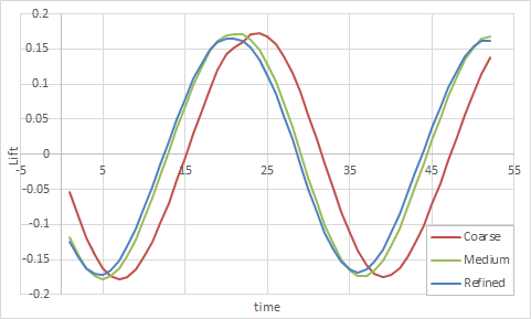
On the following figure, the red arrow shows the period of the coarse mesh.

Using a threshold of 1% change between meshes, the Nusselt number and drag coefficient values are mesh-independent on all three meshes, but the Strouhal number is not mesh-independent until the medium mesh. Thus, mesh-independent results are obtained on the medium mesh.
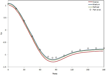
On the following figure, the mean pressure coefficient Cp plotted over the surface of the cylinder is compared with the results from Park et al. [26]. The pressure coefficient is time averaged over one vortex shedding period (∆ts = 1/f).

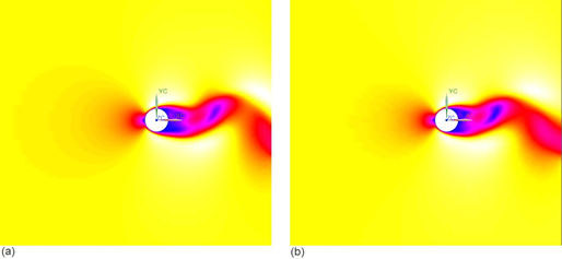
For reference, the velocity contour over the circular cylinder are compared on the following figure for the refined and coarse meshes at t = 30 seconds.

