Fan boundary condition for energy equation
The flow solver allows you to specify different temperature boundary conditions depending on the type of fan used.
Specified temperature
The fluid temperature can be specified as a boundary value on inlet flow only. The temperature imposed can either be the ambient temperature or specified temperature.
Temperature change from extract to return
For recirculation loop, you can specify a temperature change, ΔT, from the extract side of the fan to the return side of the fan as:
This is equivalent to specifying the value of the return temperature, Treturn:
Heat generation
The heat generation condition is in fact applied as a temperature specification at the exhaust side, Textract, or return side, Treturn, of the fan.
Heat generation can be specified on internal fans as well as on recirculation loops. The amount of heat generated by the fan can be expressed as:
- ṁ is the mass flow rate through the fan.
- Cp is the specific heat at constant pressure of the fluid.
- ΔT = Texhaust - Tintake for internal fans.
- ΔT = Treturn - Textract for recirculation loops.
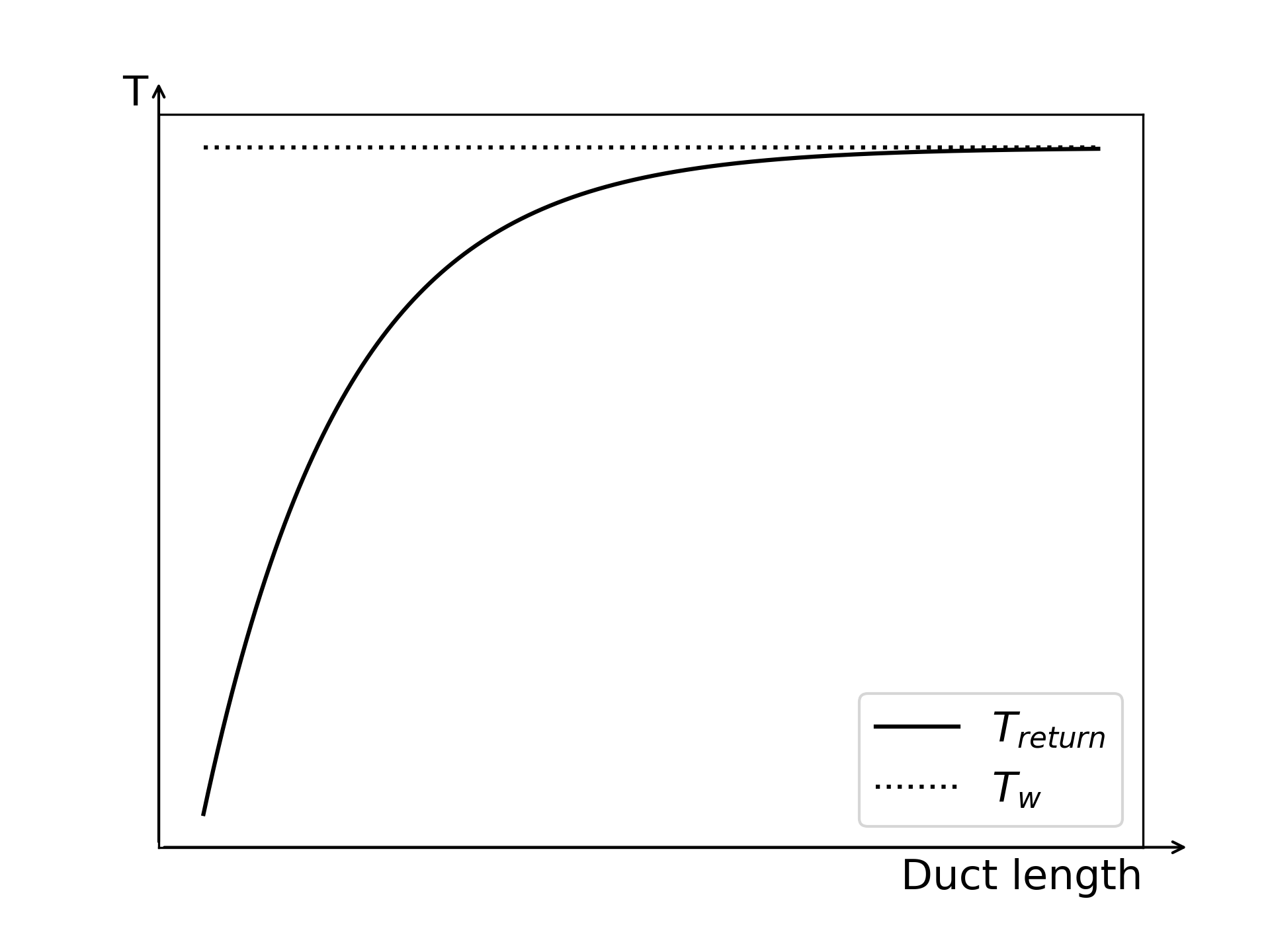
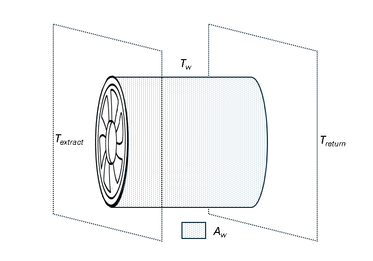
Convective heat exchange
- A virtual duct connects the extract side to the return side.
- The duct walls are in perfect contact with the environment maintained at a specified temperature Tw.
- There is a fully developed laminar flow in the duct.
Under these assumptions, the heat transfer is governed by the log-mean temperature difference equation:
- Aw is the duct wall surface area.
- h is the convective heat transfer coefficient.
The following diagram shows how the fluid return temperature changes along the length of the duct as it flows through the duct, gradually approaching the wall temperature due to convective heat exchange. In this example, Textract < Treturn, though the opposite case is also possible.