Radiation patches
Radiation patches are used to accelerate the solution of radiative heat transfer.
Two methods are available to reduce the computational cost of radiative heat-transfer calculations: one applies patching during the radiative exchange solution, and the other applies patching before view-factor computation. Both methods rely on grouping adjacent elements into radiation patches; however, they differ in how and when the patching is applied within the solution process.
Radiation patching during solution
When the Use Radiation Patches option is enabled on the radiation parameters page, adjacent Oppenheim elements are temporarily merged during the radiative exchange calculation. The Oppenheim method models radiative heat transfer by tracking the radiosity of each surface element through automatically created non-geometric Oppenheim elements that are included in the thermal solution matrix.
The governing equation for radiative exchange in an enclosure using this method is:
Where:
- εk is the emissivity of surface element k.
- Tk is the temperature of surface element k.
- To,k is the radiosity temperature of element k.
- Fkj is the view factor from element k to element j.
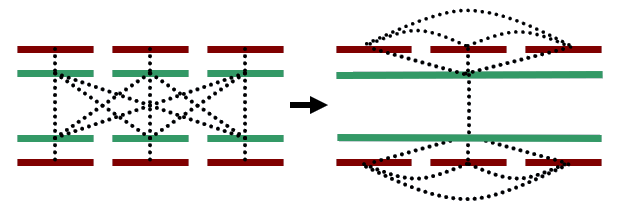
The concept of coarse radiation patches is introduced to improve computational efficiency. In this approach, the Oppenheim elements (2) of several adjacent radiative surface elements (1) are merged into a single patch (3).
The solver scans the finite element mesh and automatically groups elements into patches based on the following criteria:
- Elements must share at least one common node to be included in the same patch.
- Patches cannot span across physical barriers, such as fences in the mesh.
- All elements within a patch must have identical radiative characteristics, for example, emissivity, or reflectivity.
- The angle between the normals of adjacent elements must not exceed a specified limit, which is by default 15°.
When you use this option, the number of view factors is unchanged, and number of radiative conductances is reduced.
However, this process can introduce false conduction paths—unintended thermal connections that do not physically exist. When multiple elements are patched together, especially across misaligned surfaces, the solver may incorrectly assume thermal connectivity between elements. To correct this, the solver introduces negative conductance terms between patched elements. These terms eliminate the artificial thermal pathways created by the patching process.
Radiation patches before view factors computation
When you use the PATCH ELEMENTS FOR VIEW FACTORS CALCULATIONS advanced parameter, the thermal solver groups the elements before the view factor calculation. Therefore, view factors and radiative conductances are calculated for the created patches instead of the elements.