Supported element types for radiation
Radiating elements may be defined with 1 to 4 corner nodes. The elements may be linear or parabolic.
-
A 1-node element is a sphere, with a defined surface area.
-
A 2-node element is a circular cylinder, with a defined surface area per unit length when used as a beam. For the edge of an axisymmetric 2D element, a 2-node element represents a segment of a ring with a defined surface area based on its radius and length.
-
A 3 or 4-node element must be planar, unless it is a parabolic element. Its surface normal orientation is defined by the ordering of its nodes. If the nodes are seen in a counterclockwise order, the element faces the viewer.
To model the reverse side of a planar element, you must create a separate element with, or define the reverse side properties.
If an element has midside nodes defined, it will be considered as a parabolic element. During ray-tracing calculations, the curvature of the parabolic elements is considered when calculating the point of interception and the direction of the reflected rays.
Only elements with positive or zero emissivities take part in radiation calculations. Solid elements are not recognized by the thermal solver for view factor calculation.
-
An element may be flagged as non-radiating, in which case it is ignored for radiative calculations, but is recognized for thermal coupling calculations, even for creating radiative thermal couplings.
-
An element may be flagged as non-shadowing, in which case it will not shadow other elements during radiation calculations.
-
An element may be flagged as non-emitting, in which case neither it nor its reverse side can emit radiation or shadow radiation calculations.
-
Elements with negative solar absorptivity values are not recognized for solar view factor, planet view factor, or albedo view factor calculations.
0D elements
For radiation modeling, the solver interprets OD element as a sphere with effective diameter, and uses this configuration to determine view factors.
Beam elements
A beam element is modeled as a cylinder, and the solver approximates its surface by generating several internal flat elements. The nodes of these internal elements facet the surface of the circular beam. Specifically, the solver subdivides the beam into 6 internal elements for deterministic and Monte Carlo methods, and into 10 for hemicube rendering and GPU methods.
The GPU ray tracing method ignores the specular properties of beams and converts the specular portion into diffuse reflectivity properties.
When the solver closes beam ends, it adds internal elements to its ends with thermo-optical properties depending on the radiation calculation method. The solver creates 10 triangular elements at each beam end for hemicube rendering, 5 quadrilateral elements for the GPU method, and 2 quadrilateral elements for the deterministic and Monte Carlo methods.
The following table describes the behavior of beam element ends based on radiation calculation methods.
| Hemicube rendering | Deterministic | Monte Carlo | GPU ray tracing | GPU view factors | |
|---|---|---|---|---|---|
| Default treatment of beam ends | Closed | Open | Open | Open | Open |
| Thermo-optical properties of internally created elements on the beam's bottom side | Yes | Yes | Yes | No | No |
| Thermo-optical properties of closed beam ends | Zero emissivity when the close end of beam option is
selected Beam thermo-optical properties when the close end of beam option is cleared |
Zero emissivity | Zero emissivity | Beam thermo-optical properties | Beam thermo-optical properties |
Axisymmetric elements
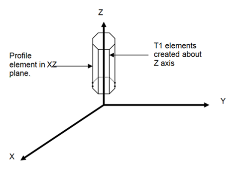
If an element is specified to be axisymmetric, it lies in the XZ plane. To allow the calculation of 3D radiative phenomena, N planar elements rotated about the global X, Y, or Z axis are created internally in the thermal solver for each profile element defined on the relevant plane. N defaults to 8. The N elements' view factors and areas are merged by the solver.

GPU-based methods do not support axisymmetric, chocking, or plane stress elements if these elements are part of a radiation request.
Warpage angle
Each linear quadrilateral element has a warpage angle calculated, which is the degree of departure from planarity of the element's surface. If the element's warpage angle is greater than 0.1 degrees, it is flagged as warped. Warped elements are treated differently in a number of different procedures. It is not recommended for a model to have warped linear elements. Should the effects of element curvature be desired for ray-tracing calculations, parabolic elements should be used.
