Modeling orbital heating and radiation to environment for spacecrafts
This article explains how to model solar heating and radiative exchange with the environment for spacecrafts in low Earth orbit (LEO).
Radiative fluxes for LEO spacecrafts
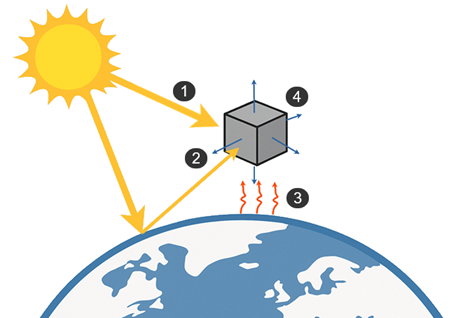
The LEO spacecraft is subject to several radiative fluxes. It gains energy from:
- Direct solar flux (1)
- Earth’s reflected solar radiation (albedo) (2)
- Thermal infrared radiation (IR) emitted by the Earth (3)
At the same time, the spacecraft loses energy by radiative cooling to deep space (4), emitting infrared radiation from its external surfaces toward the cold background of space. The thermal design balances these incoming and outgoing radiative fluxes to keep spacecraft component temperatures within allowable limits.
For each surface element of the spacecraft:
- If the element sees the Sun or Earth, the heating object applies the corresponding incoming flux to the element.
- If the element does not see the Sun or Earth, the incoming flux from the heating object is zero.
Modeling incoming radiative fluxes
You can account for all incoming radiative fluxes for LEO spacecrafts using an Orbital Heating simulation object, the software computes the right-hand side of the energy balance equation for each surface element, the incoming heat inputs from the direct Sun, Earth IR, and Earth albedo. It:
- Computes the direct solar heat input by multiplying the solar flux by the surface area, the surface absorptivity, and the view factor between the surface and the Sun, which represents the effective area perpendicular to the Sun vector.
- Computes the view factors from each element to Earth.
- Combines these view factors with the specified Earth IR flux to obtain the incident IR heat flux. Earth IR heat flux is weighted by the spacecraft–Earth view factor VFSC-Earth.
- Computes the effective albedo contribution based on illuminated Earth geometry, spacecraft altitude and attitude.
The Orbital Heating simulation object is responsible only for incoming environmental fluxes. It does not compute the radiative cooling of the spacecraft to deep space.
Modeling outgoing radiative flux
The radiative cooling of the spacecraft to deep space is modeled using one of the following:
- A Simple Radiation to Environment constraint applied to all faces of the spacecraft with a known emissivity.
- An Enclosure Radiation type of the Radiation simulation object with the Include Radiative Environment option enabled.
For all positions throughout the orbit, there is no need to modify the radiation to environment constraint or radiation enclosure selections. You do not need to split the external geometry into separate groups for illuminated and non-illuminated faces. You can define a single group that contains all external surfaces:
- Faces that see the Sun or Earth: radiate to the environment and receive environmental fluxes.
- Faces that do not see the Sun or Earth: radiate to the environment without environmental heat input.
When you change spacecraft attitude or orbit parameters between simulations, the solver automatically updates which faces receive environmental heating while all external faces continue to radiate to the environment.
When you use a Enclosure Radiation and enable the Include Radiative Environment option, the solver:
- Computes detailed view factors between all participating surfaces.
- Computes view factors from each surface to the external environment.
- Solves the full radiative exchange, including multiple reflections and self-shielding effects.
This approach:
- Is computationally expensive.
- Provides higher fidelity for complex re-radiating geometries.
- Captures local minimum and maximum surface temperatures more accurately.
The Simple Radiation to Environment constraint uses a gray body view factor (GBVF) to approximate the radiative coupling of a region to the environment.
This approach:
- Is computationally efficient.
- Uses a single effective parameter (GBVF) for all elements in the selected region.
- Is an approximation of the detailed view factor solution.
If you keep the default GBVF value of 1, you are assuming that the region sees the environment with an effective view factor of 1 and has no significant shielding or re-radiation effects. For complex external geometries, the true effective GBVF may differ substantially from 1.
When you compare results between an Enclosure Radiation with the Include Radiative Environment check box selected, and a Simple Radiation to Environment constraint with a specified GBVF value, any temperature differences are typically due to a mismatch between the specified GBVF values and the equivalent coupling computed by the detailed enclosure. The two approaches should produce similar global heat balances and similar average temperatures when the following conditions are satisfied:
- The same external geometry is included in both setups.
- The same Orbital Heating object is used for heat inputs.
- The specified GBVF value in the Simple Radiation to Environment constraint matches the effective coupling to the environment from the detailed enclosure.
Local temperatures and gradients may still differ because the Simple Radiation to Environment constraint applies a single GBVF value over the entire region.
To obtain a realistic GBVF value for a region:
- Run a simulation with a standard radiation enclosure that includes the region of interest and the external environment.
- Request a radiation report of type Between Regions.
- In the report, identify the RadK value between the selected geometry and the external radiative environment.
- Use this RadK value as the equivalent GBVF for the Simple Radiation to Environment constraint applied to the same region.
This procedure ensures that the simplified constraint approximates the total heat exchange with the environment computed by the full enclosure solution. However, a single GBVF value cannot reproduce all local temperature variations in complex geometries.
To choose between two approaches, use the following guidelines:
- If the external geometry is simple and performance is critical, a Simple Radiation to Environment constraint with an appropriate GBVF can be sufficient.
- If the external geometry includes significant re-radiation and shielding between components, an Enclosure Radiation with the selected Include Radiative Environment generally provides more accurate results.
Heat balance of spacecrafts in LEO during eclipse

In the combined Space–spacecraft–Earth radiative network, the net heat rate for a surface element in eclipse can be written as:
where:
- QSC-S is the heat from spacecraft to Space (SC-Space).
- QSC-E is the heat from the spacecraft to Earth (SC-E).
The radiative resistances from the spacecraft to deep space and from the spacecraft to Earth are represented as follows:
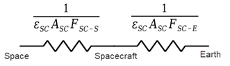
where εSC is the emissivity of the spacecraft surface, ASC is the radiating area of the spacecraft surface, and F is the view factor.
Using the radiative conductance definition Q = GΔE, where E = σT4 the balance becomes:
where:
- GSC-S is a radiative conductance between the spacecraft surface and deep space.
- GSC-E is a radiative conductance between the spacecraft surface and the Earth.
Substituting the radiative conductances for SC–Space and SC–E links and using E = σT4 gives:
With the following relations:
we obtain:
In this final equation, the heat leaving the spacecraft (left-hand side) no longer depends explicitly on a view factor toward the Earth. The Earth has been removed from the field of view and replaced by a weighted incident heat flux.