VVF24 - Turbulent flow through a 180 degree pipe bend
| Solution | Test case |
|---|---|
| RNG K-Epsilon | SVTEST217 |
| Realizable K-Epsilon | SVTEST218 |
| Standard K-Epsilon | SVTEST219 |
Description
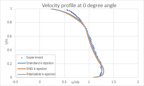
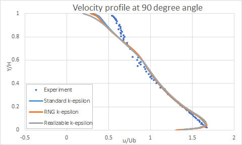
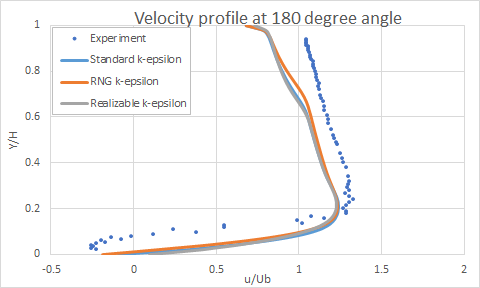
This validation case examines the turbulent flow in a U-bend channel for three types of turbulence models: Standard k-epsilon, RNG k-epsilon, and Realizable k-epsilon. This case studies streamwise velocity profiles of the turning region in the channel at three different locations: 0°, 90°, and 180° angles. The results computed by flow solver are compared with the Monson and Seegmiller [27] experimental data.
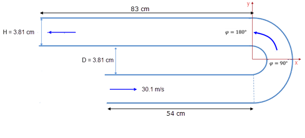
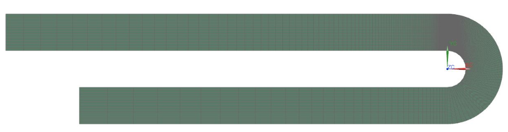
Geometry
The geometry consists of a U-bend rectangular channel of 3.81 cm in height and 3.81 cm in width. The U-bend has a gap spacing equal to 3.81 cm. The entrance section is 54 cm long. After the bend, the downstream section is 83 cm.
Simulation model
This model uses the Advanced Flow solution type.
The swept mesh is made of hexahedral elements. The following mesh controls are used:
- Lower part of the duct: 35 cells, biasing ratio 0.93
- Inlet and outlet: 48 cells, no biasing
- Inner circle: 140 cells, biasing ratio 1.02
- Outer circle: 140 cells, biasing ratio 1.03
- Upper part of the duct: 136 cells, biasing ratio 0.96
- Inlet and outlet: 48 cells, no biasing
The fluid is modeled using air at 12 bar and -9° with the following properties:
- Mass density: ρ = 15.998 kg/m3
- Thermal conductivity: k = 0.024116 W/m·ºC
- Dynamics viscosity: µ = 1.6936e-5 kg/mm s
- Coefficient of thermal expansion: β = 0.00397 °C-1
- Gas constant: R = 287 J/kg·K
The following boundary conditions are applied:
- Flow Boundary Condition: Inlet Flow on the lower end of the channel with a velocity of 31.1 m/s
- Flow Boundary Condition: Opening on the opposite end of the channel
- Flow Surface: Boundary Flow Surface on the inner surface of the channel using the Wall Function treatment
- Flow Surface: Boundary Flow Surface on the outer surface of the channel using the Wall Function treatment
Th following solution options are set:
- Turbulence Model:Standard K-Epsilon, RNG K-Epsilon or Realizable K-Epsilon
- Solution Type: Steady State
- Initial conditions: Uniform with the intensity of 0.01 and eddy length of 0.07 mm set in the Turbulence Characteristics modeling object.
The following solver parameters are selected:
- 3D Flow Solver: Physical steady-state with time step = 0.001 s
- 3D Flow Solver: RMS Residuals = 1e-8
- 3D Flow Solver: Momentum Advection scheme: SOU with limiter 0.5
Results
The following figures show the comparison of the flow solver results for Standard k-epsilon, RNG k-epsilon, and Realizable k-epsilon turbulence models with the experimental results for the velocity profile at 0°, 90°, 180° angles, respectively.